6 layers91.6 × 50.6 mm
Smokebreak
offgridevices/offgrid-hardware
Open hardware from OffGrid Devices. One folder per board. CERN-OHL-S.
208 partsCERN-OHL-S-2.0
 offgridevices/offgrid-hardware
Open hardware from OffGrid Devices. One folder per board. CERN-OHL-S.
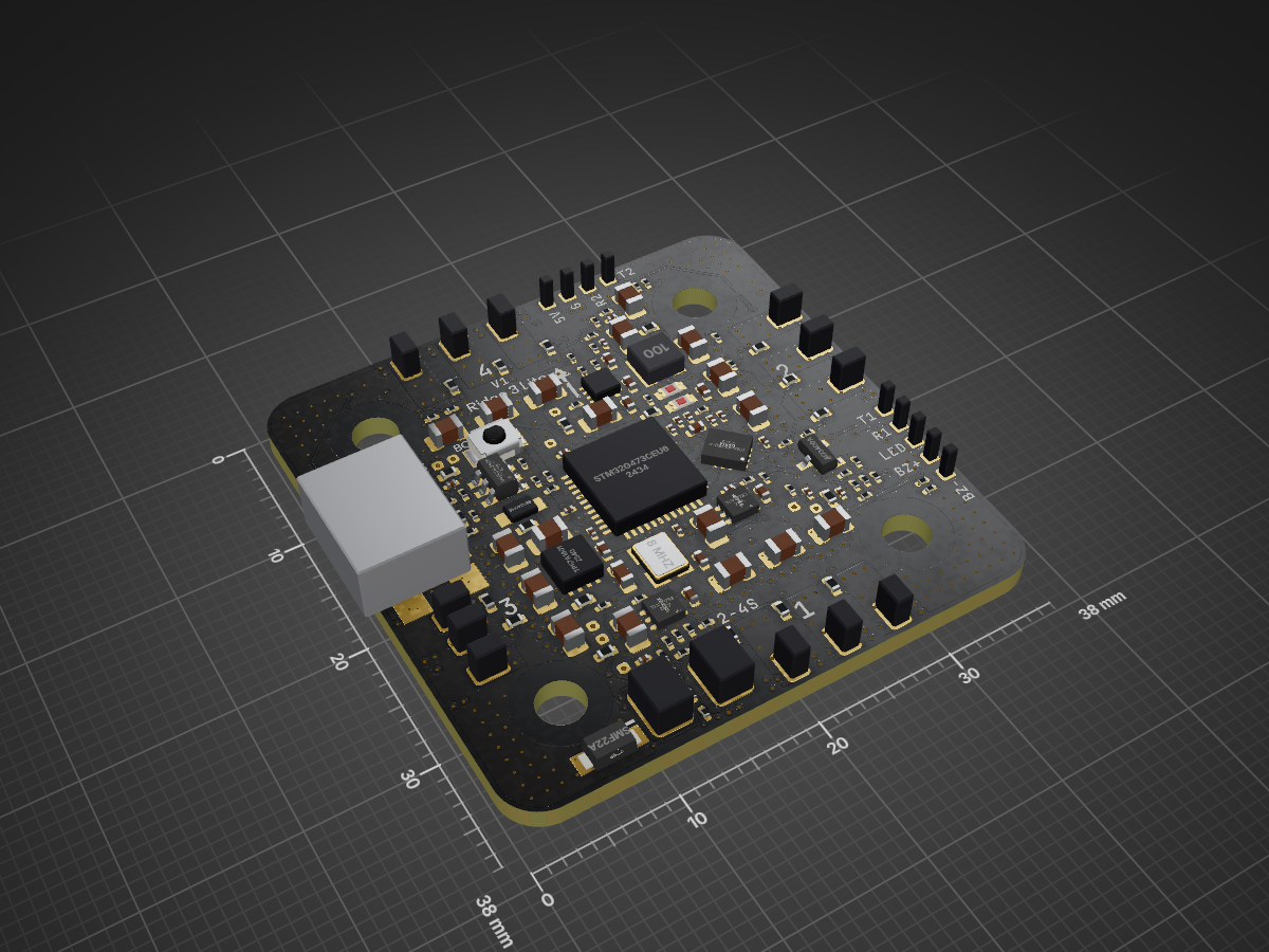
Ridge3-lite is an open-source printed circuit board by offgridevices, from the offgridevices/offgrid-hardware repository on GitHub, published under the CERN-OHL-S-2.0 licence. It is an 8-layer board of 38 × 38 mm with 260 parts on 188 nets, routed with 2,510 tracks and 777 vias.
It is built around the STM32G071GBU6, STM32G473CEU6 and DRV8300DRGER-MS, with the TPN2R304PL,L1Q, TLV76733DGN and AO3400A among its other parts. Its parts include 96 resistors, 71 capacitors, 24 transistors and 1 crystal. It belongs with the STM32 boards of this library.


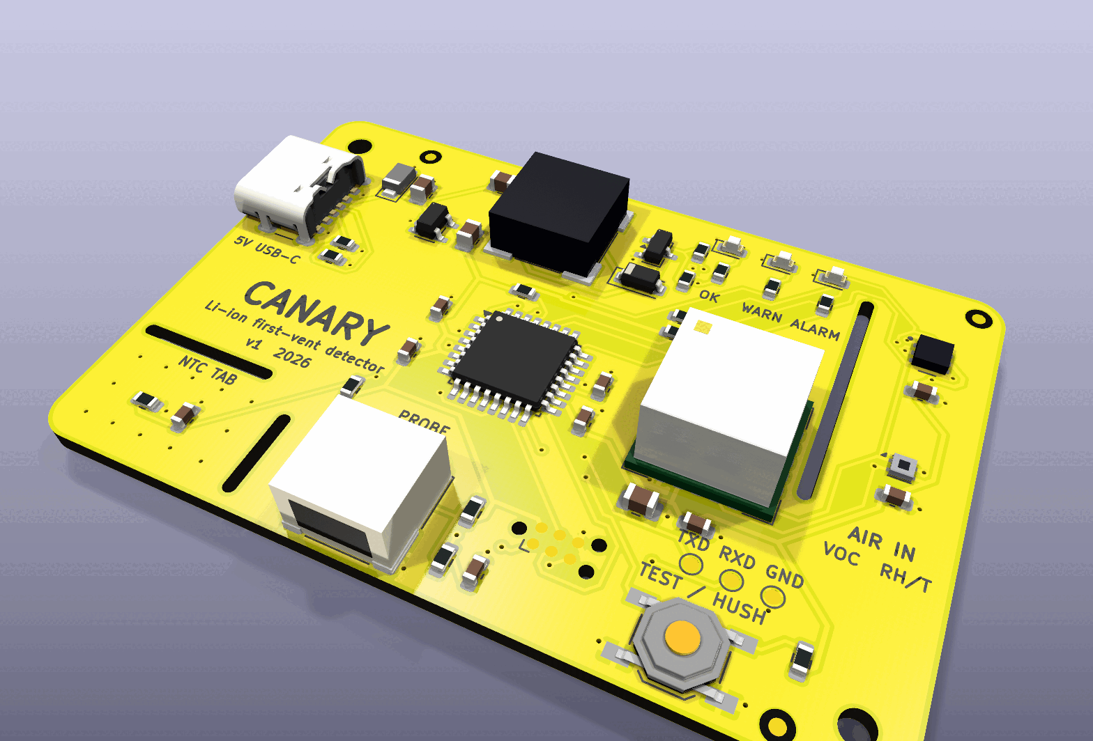
Status: designed and verified in simulation, not yet built. Every gate below passes on this revision; no board has been assembled or powered yet.
This folder always holds the latest revision; an ordered revision stays at
its order tag (docs/versioning.md).
| Revision | What changed | Status | Order tag |
|---|---|---|---|
| 1.0 | first design: SGP40 + SCD41 + SHT40 + NTC tab, ATmega328P, 100 dB sounder, 60 × 40 mm, 2 layers | designed and simulation-verified, not yet built | — |
A 60 × 40 mm board you put next to (or on) an e-bike or scooter battery while it charges. It watches for the first vent — the moment a failing cell boils off electrolyte as solvent vapour and CO₂ — which comes before self-heating, thermal runaway and smoke. A smoke alarm reacts at the end of that chain; Canary is built to react near its start.
Grid storage and EV packs already carry off-gas detectors (Honeywell BES, Li-ion Tamer). The battery charging in a hallway has nothing. Canary is that detector as an open, cheap, USB-powered board you can order fully assembled.
It fuses three kinds of evidence and needs two at once to alarm:
| Evidence | Sensor | Fires on | Alone it means |
|---|---|---|---|
| Gas | Sensirion SGP40 MOX (on the isolated sensor head) | raw signal ≥ 700 ticks below its learned clean-air baseline (strong ≥ 2500) | WARN (cleaning spray, solvents) |
| CO₂ | Sensirion SCD41 photoacoustic | rise ≥ 250 ppm/min or ≥ 1500 ppm over baseline (strong ≥ 1200 ppm/min or ≥ 4000 ppm) | WARN (someone breathing on it) |
| Heat | NTC on the thermal tab (or remote probe) | ≥ 50 °C, or ≥ 1 °C/min above 35 °C (strong: ≥ 65 °C, or ≥ 3 °C/min above 30 °C) | WARN; strong heat alone → ALARM |
ALARM = gas and CO₂ (one strong), or heat and any gas evidence, or strong heat alone; held 3 s before it sounds, latched for at least 60 s. Outputs: green breathing (watching), amber (one kind of evidence), red flashing + 100 dB 4 kHz sounder in the smoke-alarm T3 pattern. The button self-tests in normal state and hushes for 2 minutes in alarm — the hush ends early if the evidence gets worse.
Product video: a narrated 4-minute explainer, built by video/ and
published rather than committed (video/README.md).
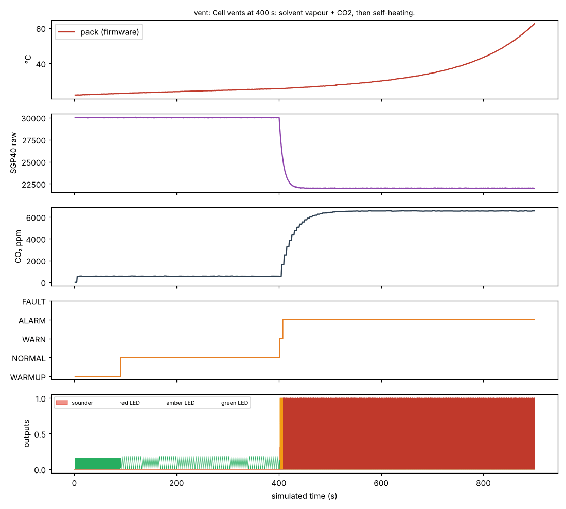
The real firmware, on a simulated ATmega328P with virtual sensors, catching
a vent at 400 s (alarm 7.6 s later) — sim/hil/:
| Requirement | How it is checked | Met? |
|---|---|---|
| Order from PCBWay, arrive assembled and working | Gerbers + PCBWay BOM + CPL + firmware HEX in production/; all parts on top; every part has an MPN | Yes (files); hardware not yet built |
| Parts in production today | Distributor check 2026-10-14, docs/sourcing-2026-10-14.md | Yes — one NRND part replaced (NTC) |
| Latest KiCad | KiCad 10.0.6 (kicad/kicad:10.0.6-full), current stable | Yes |
| Schematic clean | kicad-cli sch erc: 0 violations | Yes |
| Board clean, fab's limits | kicad-cli pcb drc --schematic-parity --severity-all: 0 errors, 0 warnings, 0 unconnected against PCBWay 2-layer limits (with margin) | Yes |
| Clean copper, wide enough for its current | check_geometry.py: no corner sharper than 45° (the router's six right angles mitered by miter.py); every power track ≥ 2.4× its IPC-2221 width at a 10 °C rise | Yes |
| Schematic = circuit = board = firmware | check_netlist.py (27 nets, 0 mismatches), DRC parity, check_pins.py (11 pins, 0 mismatches) | Yes |
| Detects a vent within seconds, ignores single-cause events | HIL simulation of the real firmware: vent → ALARM in 7.6 s; spray, breath → no alarm; still detecting after 100 min of charging; 65/65 checks across 9 scenarios | Yes, in simulation |
| Sounder driver safe | ngspice: drain clamped at 5.4 V on 5 V, clamp diode ≤ 0.34 A, VBUS dip ≥ 4.95 V, for 0.5–4 mH coils | Yes |
| Pack temperature good enough at the thresholds | Tolerance stack-up: ≤ 1.24 °C worst case at 65 °C; rate quantum 0.2 °C/min | Yes |
| Runs from any USB charger | 23.5 mA watching, ~520 mA worst-case peak in alarm | Yes (≤ 900 mA) |
production/canary-gerbers.zip.
production/canary-bom-pcbway.csv (MPN, maker, LCSC # for reference, notes)production/canary-cpl.csv; drawing: production/canary-assembly.pdfproduction/canary.hex to U2 (ATmega328P) through the Tag-Connect TC2030
pads (J2, standard 6-pin AVR ISP pinout), with fuses
lfuse 0xE2, hfuse 0xD9, efuse 0xFD (internal 8 MHz, no clock divider,
brown-out 2.7 V). To do it yourself: a USBasp + TC2030-IDC-NL cable, then
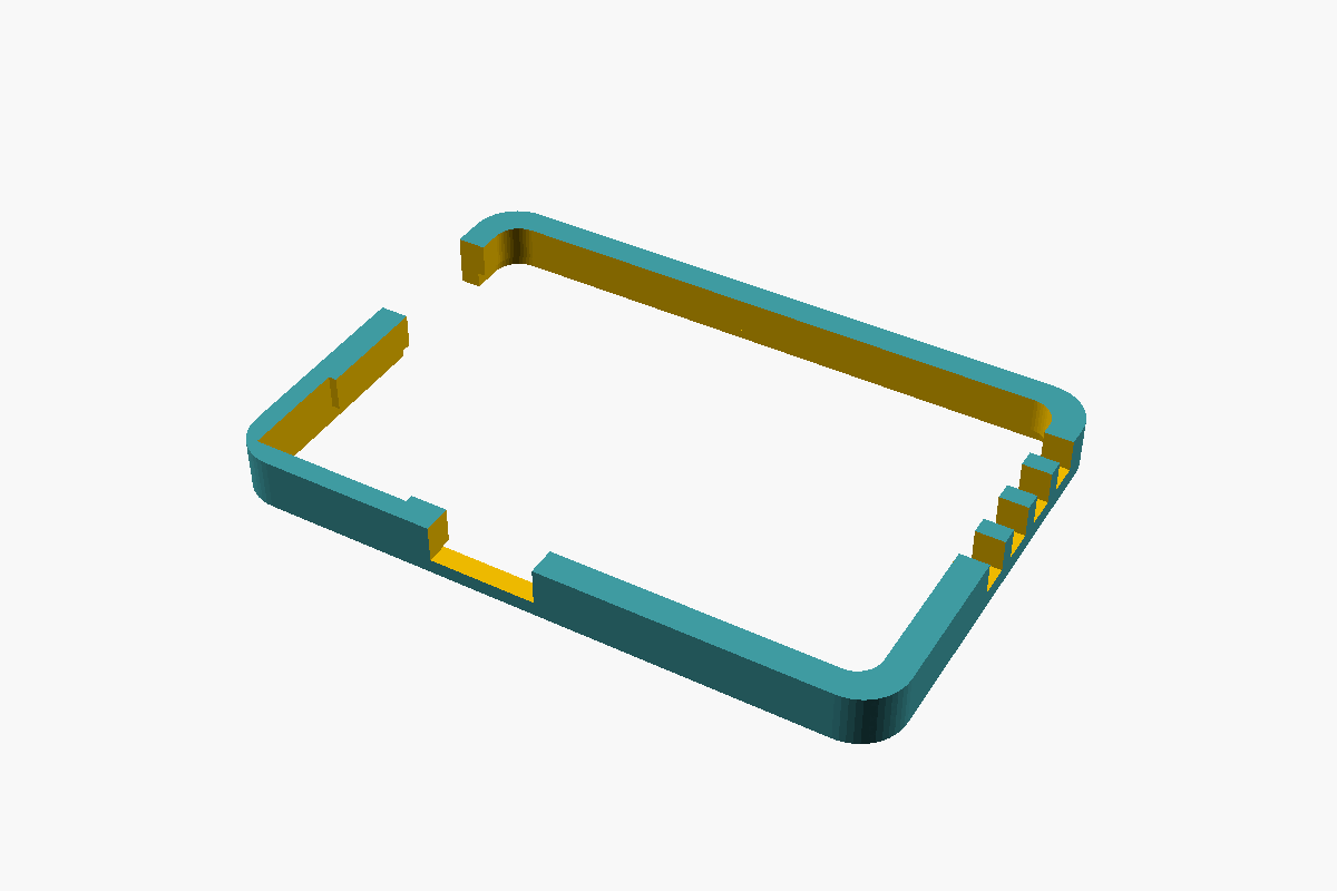
make -C firmware flash.enclosure/print/canary-v1-bumper.stl is an optional printed frame (PLA/PETG, no
supports, 64 × 44 × 5 mm). The board presses in from below; its underside
stays flush with the frame's so the thermal tab still lies on the pack, and
the USB-C, probe connector and the sensor head's air path stay open.
t= st= tp= ... sraw= co2= rate= dtdt= e= f=).firmware/src/detect.h may move.src/models3d.py (KiCad 10.0.6 ships none).| Path | What |
|---|---|
production/ | Gerber zip, PCBWay BOM, CPL, netlist, assembly + schematic PDFs, firmware HEX |
canary.kicad_sch, canary.kicad_pcb, canary.kicad_pro | KiCad 10 design (generated) |
src/ | the design source: circuit.py (every part and net), schematic.py, board.py, miter.py, finish.py, fab.py, checks |
firmware/ | AVR C firmware (detect.c is the detector logic) |
sim/hil/ | simavr hardware-in-the-loop harness + scenarios |
sim/spice/, sim/analysis/ | sounder driver SPICE, NTC/power/I²C analyses |
video/ | the scripts that build the narrated product video (the MP4 is published, not committed) |
web/ | the interactive bench page (build_page.py → one HTML file); its detector is a port of detect.c checked equal to the firmware second by second |
mechanical/ | STEP model (zipped) |
enclosure/ | 3D-printable bumper: bumper.scad, and print/canary-v1-bumper.stl |
TESTS.md, docs/decisions.md | every test with results; the trade-offs |
Needs docker (kicad/kicad:10.0.6-full), Java + xvfb (Freerouting 1.9.0 at
/opt/fr/freerouting-1.9.0.jar or FREEROUTING_JAR), avr-gcc, Python 3.
python3 src/make.py                 # schematic, ERC, netlist gate, place, route, DRC gate, fab
python3 src/make.py sch finish fab  # without re-routing (the routed board in out/ is reused)
make -C firmware                    # firmware only
cd sim/hil && gcc -O2 -I<simavr>/simavr/sim ... && python3 scenarios.py   # see sim/hil/README.md
Routing is done by Freerouting and is not bit-for-bit repeatable, so the
committed canary.kicad_pcb is the design of record: CI rebuilds the
fab outputs from it and checks they match what is committed.
| Qty | Value | Footprint | References |
|---|---|---|---|
| 26 | 100nF | C_0201_0603Metric_L | C13, C14, C15, C16, C17, C18, C19, C22, C101, C109, C110, C111, C201, C209, C210, C211 +10 |
| 24 | TPN2R304PL | TSON-8_L3.1-W3.1-P0.65-LS3.3-BL-EP | Q1AH, Q1AL, Q1BH, Q1BL, Q1CH, Q1CL, Q2AH, Q2AL, Q2BH, Q2BL, Q2CH, Q2CL, Q3AH, Q3AL, Q3BH, Q3BL +8 |
| 23 | 10k | R_0201_0603Metric_L | R16, R105, R110, R115, R118, R120, R205, R210, R215, R218, R220, R305, R310, R315, R318, R320 +7 |
| 16 | 4.7uF | C_0805_2012Metric | C1, C8, C10, C11, C104, C106, C108, C204, C206, C208, C304, C306, C308, C404, C406, C408 |
| 15 | 1uF | C_0402_1005Metric_L | C4, C7, C9, C103, C105, C107, C203, C205, C207, C303, C305, C307, C403, C405, C407 |
| 13 | 10R | R_0201_0603Metric_L | R10, R102, R107, R112, R202, R207, R212, R302, R307, R312, R402, R407, R412 |
| 13 | 10k | R_0402_1005Metric_L | R6, R103, R108, R113, R203, R208, R213, R303, R308, R313, R403, R408, R413 |
| 12 | 2.2k | R_0201_0603Metric_L | R104, R109, R114, R204, R209, R214, R304, R309, R314, R404, R409, R414 |
| 12 | 22R | R_0201_0603Metric_L | R101, R106, R111, R201, R206, R211, R301, R306, R311, R401, R406, R411 |
| 12 | PAD_MOTOR | PAD_MOTOR | P_M1A, P_M1B, P_M1C, P_M2A, P_M2B, P_M2C, P_M3A, P_M3B, P_M3C, P_M4A, P_M4B, P_M4C |
| 10 | PAD_TP | PAD_TP | TP_3V3, TP_C1, TP_C2, TP_C3, TP_C4, TP_D1, TP_D2, TP_D3, TP_D4, TP_GND |
| 9 | PAD_SIG | PAD_SIG | P_5V, P_BZ-, P_BZ+, P_G, P_LED, P_R1, P_R2, P_T1, P_T2 |
| 6 | 1k | R_0201_0603Metric_L | R7, R13, R117, R217, R317, R417 |
| 5 | 100k | R_0402_1005Metric_L | R1, R119, R219, R319, R419 |
| 5 | 10uF | C_0603_1608Metric_L | C12, C102, C202, C302, C402 |
| 4 | 0.5mOhm | RES-SMD_1206_HCS1206 | R_S1, R_S2, R_S3, R_S4 |
| 4 | 1.5k | R_0201_0603Metric_L | R116, R216, R316, R416 |
| 4 | DRV8300DRGER | VQFN-24_L4.0-W4.0-P0.50-TL-EP2.5 | U_D1, U_D2, U_D3, U_D4 |
| 4 | HOLE | MOUNT_M2 | H1, H2, H3, H4 |
| 4 | INA186A3 | SC-70-6_L2.0-W1.3-P0.65-LS2.1-BL-1 | U_A1, U_A2, U_A3, U_A4 |
| 4 | STM32G071GBU6 | UFQFPN-28_L4.0-W4.0-P0.50-BL | U_E1, U_E2, U_E3, U_E4 |
| 2 | 100nF | C_0402_1005Metric_L | C2, C3 |
| 2 | 12pF | C_0402_1005Metric_L | C23, C24 |
| 2 | 22uF | C_0805_2012Metric | C5, C6 |
| 2 | 4.7uF | C_0402_1005Metric_L | C21, C25 |
| 2 | 5.1k | R_0201_0603Metric_L | R11, R12 |
| 2 | PAD_BAT | PAD_BAT | P_BAT-, P_BAT+ |
| 2 | TLV76733 | WSON-6_L2.0-W2.0-P0.65-TL-EP | U_LDO, U_LDOE |
| 1 | 100R | R_0201_0603Metric_L | R15 |
| 1 | 10R | R_0402_1005Metric_L | R3 |
| 1 | 10uH | IND-SMD_L3.0-W3.0_SWPA3010S | L_BEC |
| 1 | 1uF | C_0201_0603Metric_L | C20 |
| 1 | 27k | R_0201_0603Metric_L | R2 |
| 1 | 330R | R_0201_0603Metric_L | R14 |
| 1 | 62k | R_0201_0603Metric_L | R8 |
| 1 | 8 MHz | CRYSTAL-SMD_4P-L3.2-W2.5-BL | Y1 |
| 1 | 82k | R_0402_1005Metric_L | R4 |
| 1 | AO3400A | SOT-23-3_L2.9-W1.3-P1.90-LS2.4-BR | Q_BZ |
| 1 | BOOT | KEY-SMD_B3U-1000PM | SW_BOOT |
| 1 | ICM-42688-P | LGA-14_L3.0-W2.5-P0.50-TL | U_IMU |
| 1 | LMR36506R5 | VQFN-9_L2.1-W2.1-P0.50-TL | U_BEC |
| 1 | SMF22A | SOD-123FL_L2.8-W1.9-LS3.7-RD | D_TVS |
| 1 | SS1040HE | SOD-323HE_L2.0-W1.4-LS2.5-RD | D_USB |
| 1 | STM32G473CEU6 | UFQFPN-48_L7.0-W7.0-P0.50-BL-EP5.6 | U_FC |
| 1 | TPS7A1601 | SON-8_L3.0-W3.0-P0.65-TL-EP | U_GVDD |
| 1 | USB-C | USB-C-SMD_TYPE-C-16P-USB4110-GF-A | J_USB |
| 1 | USBLC6-2SC6 | SOT-23-6_L2.9-W1.6-P0.95-LS2.8-BL | U_ESD |
| 1 | blue | LED0603-RD | LED_STAT |
| 1 | red | LED0603-RD | LED_PWR |
offgridevices/offgrid-hardware
Open hardware from OffGrid Devices. One folder per board. CERN-OHL-S.

offgridevices/offgrid-hardware
Open hardware from OffGrid Devices. One folder per board. CERN-OHL-S.

offgridevices/offgrid-hardware
Open hardware from OffGrid Devices. One folder per board. CERN-OHL-S.

offgridevices/offgrid-hardware
Open hardware from OffGrid Devices. One folder per board. CERN-OHL-S.

offgridevices/offgrid-hardware
Open hardware from OffGrid Devices. One folder per board. CERN-OHL-S.

offgridevices/offgrid-hardware
Open hardware from OffGrid Devices. One folder per board. CERN-OHL-S.

offgridevices/offgrid-hardware
Open hardware from OffGrid Devices. One folder per board. CERN-OHL-S.

offgridevices/offgrid-hardware
Open hardware from OffGrid Devices. One folder per board. CERN-OHL-S.

offgridevices/offgrid-hardware
Open hardware from OffGrid Devices. One folder per board. CERN-OHL-S.

offgridevices/offgrid-hardware
Open hardware from OffGrid Devices. One folder per board. CERN-OHL-S.

cypamigon/atmos_fc
Drone flight controller based on STM32G4 with IMU (ICM-468-P), barometer (DPS-386), OSD (MAX7456) and 32MB flash memory for blackbox logging — running Betaflight.

ghostinkoma/mPBCH32M030DS0
WCH CH32M030C8U7 (QFN48) の DIP-42 MCU モジュール (ブレッドボード対応) と、差し替え式の パワー段子基板 (MOSFET ×8) の 2 枚構成です。 次のモータを駆動します。 USB-C から ESP32-C3 / Arduino のように書き込めて、USB-PD 充電器 (9〜15V) だけでもモーターを回せます。 内蔵の電流源・USB-PD・OPA/CMP を使い切る設計です…

Bemeier/bmcv
Macro CV controller for eurorack inspired by the Emblematic Systems Catalyst

OmkarTikekar0037/usb3-gigabit-ethernet-adapter
This is a repository for version control of zoho project - USB 3.1 to Gigabit Ethernet Adapter


It measures 38 × 38 mm and has 8 copper layers, 1.6 mm thick.
260 parts, built around the STM32G071GBU6, STM32G473CEU6, DRV8300DRGER-MS and TPN2R304PL,L1Q. The full list of its parts is on this page, with links to each part's symbol and footprint where PCBKit's library has them.
From the offgridevices/offgrid-hardware repository on GitHub, at the commit this page was made from: the board is products/ridge/ridge-3-lite/ridge3-lite.kicad_pcb and its schematic products/canary/canary.kicad_sch. PCBKit opens the board in the browser, with nothing to install.
Its repository publishes it under the CERN-OHL-S-2.0 licence: you may reuse it on that licence's terms (keep the author's notice, and for a copyleft licence share your changes alike).