
8 layers38 × 38 mm
Ridge3-lite
offgridevices/offgrid-hardware
Open hardware from OffGrid Devices. One folder per board. CERN-OHL-S.
260 partsCERN-OHL-S-2.0

 offgridevices/offgrid-hardware
Open hardware from OffGrid Devices. One folder per board. CERN-OHL-S.
Layercam ring is an open-source printed circuit board by offgridevices, from the offgridevices/offgrid-hardware repository on GitHub, published under the CERN-OHL-S-2.0 licence. It is a 2-layer board of 27.2 × 20.3 mm with 11 parts on 10 nets, routed with 132 tracks and 15 vias.
It is built around the TEMT6000X01. Its parts include 6 diodes, 3 resistors, 1 transistor and 1 connector.
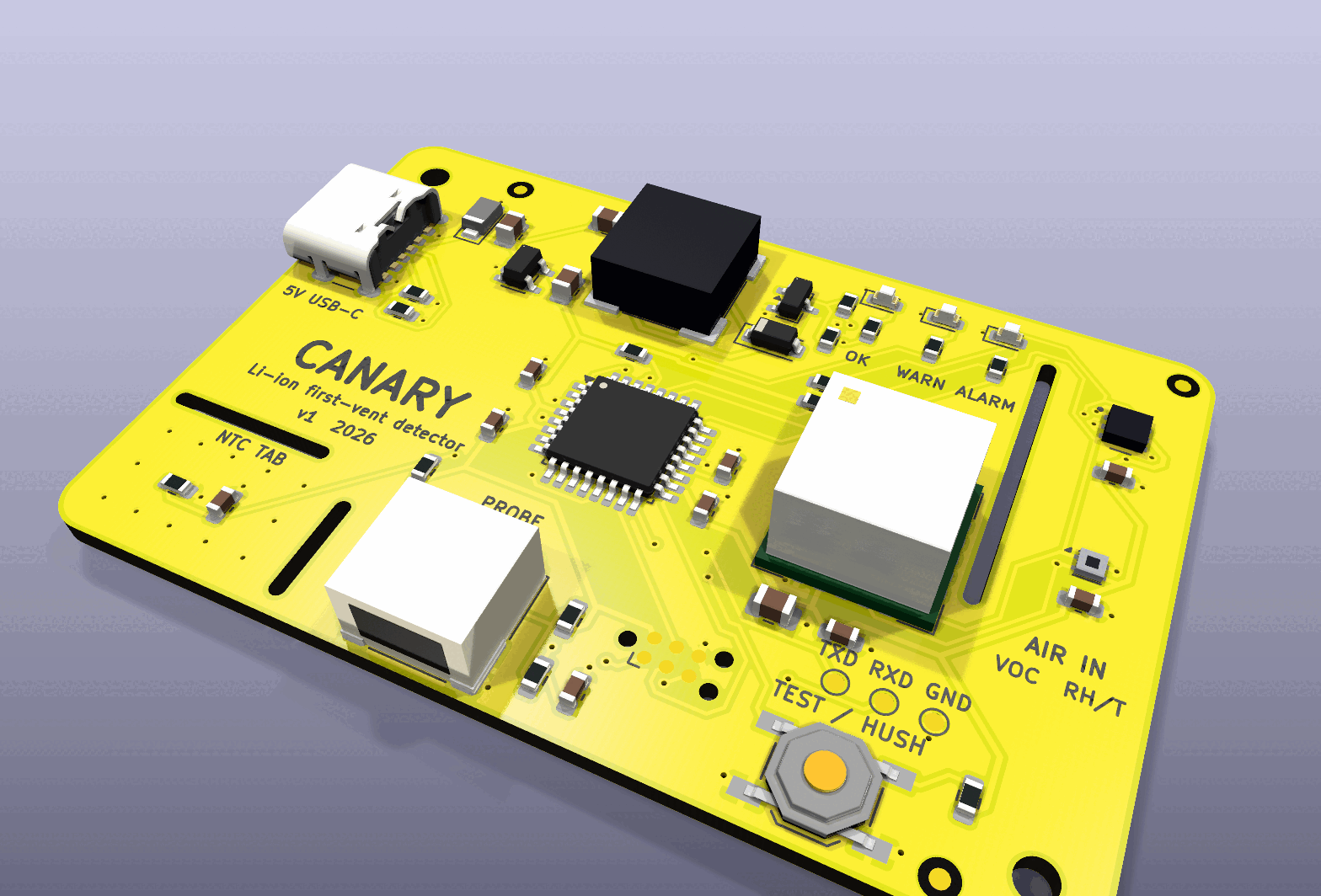
Status: designed and verified in simulation, not yet built. Every gate below passes on this revision; no board has been assembled or powered yet.
This folder always holds the latest revision; an ordered revision stays at
its order tag (docs/versioning.md).
| Revision | What changed | Status | Order tag |
|---|---|---|---|
| 1.0 | first design: SGP40 + SCD41 + SHT40 + NTC tab, ATmega328P, 100 dB sounder, 60 × 40 mm, 2 layers | designed and simulation-verified, not yet built | — |
A 60 × 40 mm board you put next to (or on) an e-bike or scooter battery while it charges. It watches for the first vent — the moment a failing cell boils off electrolyte as solvent vapour and CO₂ — which comes before self-heating, thermal runaway and smoke. A smoke alarm reacts at the end of that chain; Canary is built to react near its start.
Grid storage and EV packs already carry off-gas detectors (Honeywell BES, Li-ion Tamer). The battery charging in a hallway has nothing. Canary is that detector as an open, cheap, USB-powered board you can order fully assembled.
It fuses three kinds of evidence and needs two at once to alarm:
| Evidence | Sensor | Fires on | Alone it means |
|---|---|---|---|
| Gas | Sensirion SGP40 MOX (on the isolated sensor head) | raw signal ≥ 700 ticks below its learned clean-air baseline (strong ≥ 2500) | WARN (cleaning spray, solvents) |
| CO₂ | Sensirion SCD41 photoacoustic | rise ≥ 250 ppm/min or ≥ 1500 ppm over baseline (strong ≥ 1200 ppm/min or ≥ 4000 ppm) | WARN (someone breathing on it) |
| Heat | NTC on the thermal tab (or remote probe) | ≥ 50 °C, or ≥ 1 °C/min above 35 °C (strong: ≥ 65 °C, or ≥ 3 °C/min above 30 °C) | WARN; strong heat alone → ALARM |
ALARM = gas and CO₂ (one strong), or heat and any gas evidence, or strong heat alone; held 3 s before it sounds, latched for at least 60 s. Outputs: green breathing (watching), amber (one kind of evidence), red flashing + 100 dB 4 kHz sounder in the smoke-alarm T3 pattern. The button self-tests in normal state and hushes for 2 minutes in alarm — the hush ends early if the evidence gets worse.
Product video: a narrated 4-minute explainer, built by video/ and
published rather than committed (video/README.md).
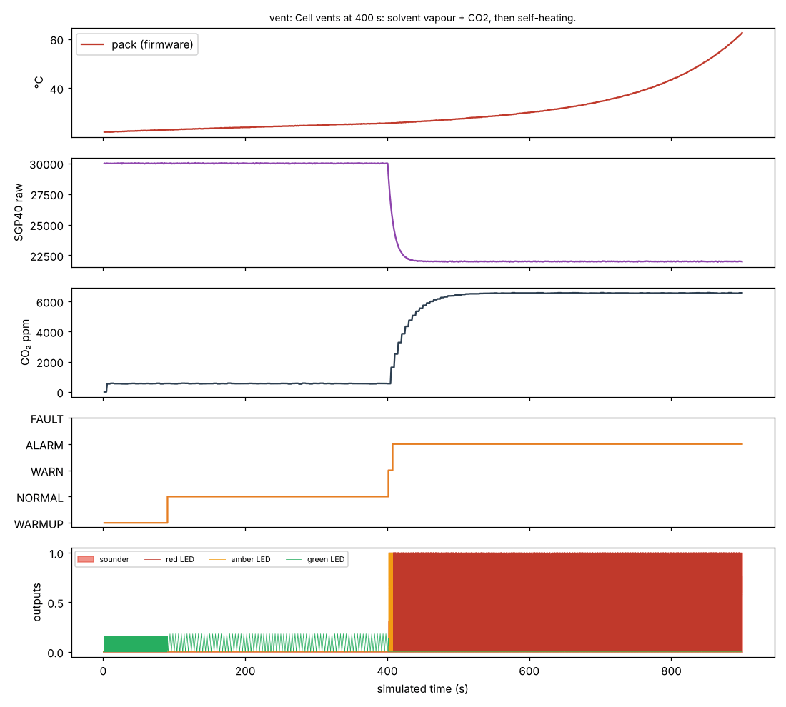
The real firmware, on a simulated ATmega328P with virtual sensors, catching
a vent at 400 s (alarm 7.6 s later) — sim/hil/:
| Requirement | How it is checked | Met? |
|---|---|---|
| Order from PCBWay, arrive assembled and working | Gerbers + PCBWay BOM + CPL + firmware HEX in production/; all parts on top; every part has an MPN | Yes (files); hardware not yet built |
| Parts in production today | Distributor check 2026-10-14, docs/sourcing-2026-10-14.md | Yes — one NRND part replaced (NTC) |
| Latest KiCad | KiCad 10.0.6 (kicad/kicad:10.0.6-full), current stable | Yes |
| Schematic clean | kicad-cli sch erc: 0 violations | Yes |
| Board clean, fab's limits | kicad-cli pcb drc --schematic-parity --severity-all: 0 errors, 0 warnings, 0 unconnected against PCBWay 2-layer limits (with margin) | Yes |
| Clean copper, wide enough for its current | check_geometry.py: no corner sharper than 45° (the router's six right angles mitered by miter.py); every power track ≥ 2.4× its IPC-2221 width at a 10 °C rise | Yes |
| Schematic = circuit = board = firmware | check_netlist.py (27 nets, 0 mismatches), DRC parity, check_pins.py (11 pins, 0 mismatches) | Yes |
| Detects a vent within seconds, ignores single-cause events | HIL simulation of the real firmware: vent → ALARM in 7.6 s; spray, breath → no alarm; still detecting after 100 min of charging; 65/65 checks across 9 scenarios | Yes, in simulation |
| Sounder driver safe | ngspice: drain clamped at 5.4 V on 5 V, clamp diode ≤ 0.34 A, VBUS dip ≥ 4.95 V, for 0.5–4 mH coils | Yes |
| Pack temperature good enough at the thresholds | Tolerance stack-up: ≤ 1.24 °C worst case at 65 °C; rate quantum 0.2 °C/min | Yes |
| Runs from any USB charger | 23.5 mA watching, ~520 mA worst-case peak in alarm | Yes (≤ 900 mA) |
production/canary-gerbers.zip.
production/canary-bom-pcbway.csv (MPN, maker, LCSC # for reference, notes)production/canary-cpl.csv; drawing: production/canary-assembly.pdfproduction/canary.hex to U2 (ATmega328P) through the Tag-Connect TC2030
pads (J2, standard 6-pin AVR ISP pinout), with fuses
lfuse 0xE2, hfuse 0xD9, efuse 0xFD (internal 8 MHz, no clock divider,
brown-out 2.7 V). To do it yourself: a USBasp + TC2030-IDC-NL cable, then
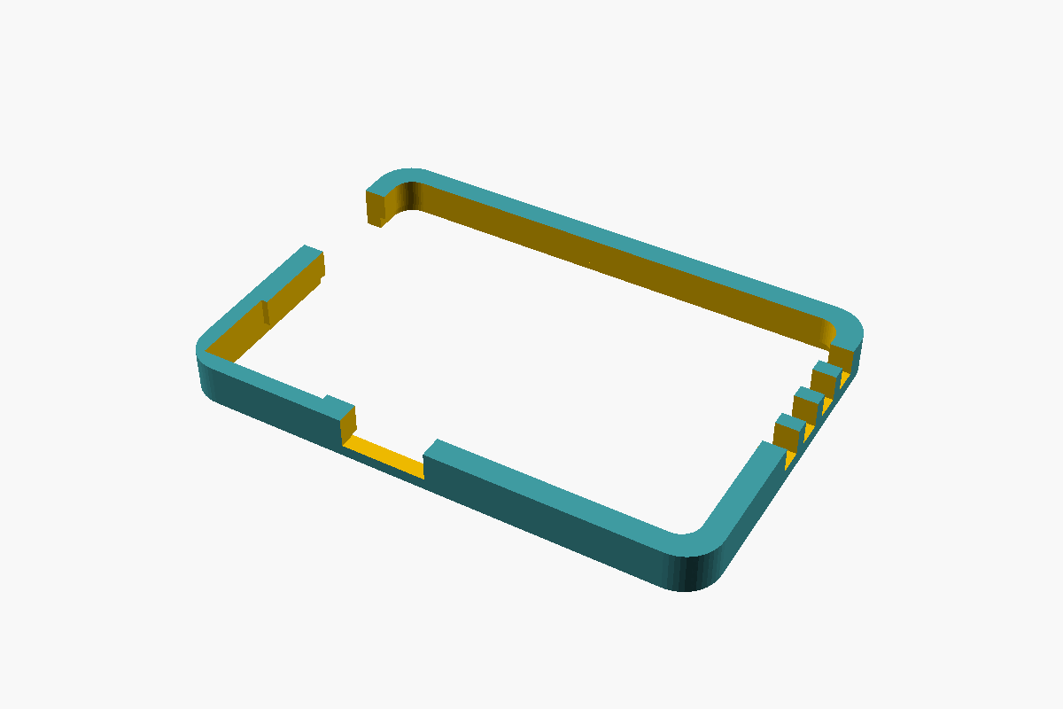
make -C firmware flash.enclosure/print/canary-v1-bumper.stl is an optional printed frame (PLA/PETG, no
supports, 64 × 44 × 5 mm). The board presses in from below; its underside
stays flush with the frame's so the thermal tab still lies on the pack, and
the USB-C, probe connector and the sensor head's air path stay open.
t= st= tp= ... sraw= co2= rate= dtdt= e= f=).firmware/src/detect.h may move.src/models3d.py (KiCad 10.0.6 ships none).| Path | What |
|---|---|
production/ | Gerber zip, PCBWay BOM, CPL, netlist, assembly + schematic PDFs, firmware HEX |
canary.kicad_sch, canary.kicad_pcb, canary.kicad_pro | KiCad 10 design (generated) |
src/ | the design source: circuit.py (every part and net), schematic.py, board.py, miter.py, finish.py, fab.py, checks |
firmware/ | AVR C firmware (detect.c is the detector logic) |
sim/hil/ | simavr hardware-in-the-loop harness + scenarios |
sim/spice/, sim/analysis/ | sounder driver SPICE, NTC/power/I²C analyses |
video/ | the scripts that build the narrated product video (the MP4 is published, not committed) |
web/ | the interactive bench page (build_page.py → one HTML file); its detector is a port of detect.c checked equal to the firmware second by second |
mechanical/ | STEP model (zipped) |
enclosure/ | 3D-printable bumper: bumper.scad, and print/canary-v1-bumper.stl |
TESTS.md, docs/decisions.md | every test with results; the trade-offs |
Needs docker (kicad/kicad:10.0.6-full), Java + xvfb (Freerouting 1.9.0 at
/opt/fr/freerouting-1.9.0.jar or FREEROUTING_JAR), avr-gcc, Python 3.
python3 src/make.py                 # schematic, ERC, netlist gate, place, route, DRC gate, fab
python3 src/make.py sch finish fab  # without re-routing (the routed board in out/ is reused)
make -C firmware                    # firmware only
cd sim/hil && gcc -O2 -I<simavr>/simavr/sim ... && python3 scenarios.py   # see sim/hil/README.md
Routing is done by Freerouting and is not bit-for-bit repeatable, so the
committed canary.kicad_pcb is the design of record: CI rebuilds the
fab outputs from it and checks they match what is committed.
| Qty | Value | Footprint | References |
|---|---|---|---|
| 6 | 850nm | LED-SMD_L3.5-W2.8-R-RD_RED-1 | D1, D2, D3, D4, D5, D6 |
| 3 | 47R | R_1206_3216Metric | R1, R2, R3 |
| 1 | SH 6 | CONN-SMD-6P-P1.00_BM06B-SRSS-TB-LF-SN | J1 |
| 1 | TEMT6000 | SENSORS-SMD_TEMT6000X01 | Q1 |
It measures 27.2 × 20.3 mm and has 2 copper layers, 1.6 mm thick.
11 parts, built around the TEMT6000X01. The full list of its parts is on this page, with links to each part's symbol and footprint where PCBKit's library has them.
From the offgridevices/offgrid-hardware repository on GitHub, at the commit this page was made from: the board is products/layercam/layercam/ring/layercam-ring.kicad_pcb and its schematic products/canary/canary.kicad_sch. PCBKit opens the board in the browser, with nothing to install.
Its repository publishes it under the CERN-OHL-S-2.0 licence: you may reuse it on that licence's terms (keep the author's notice, and for a copyleft licence share your changes alike).
offgridevices/offgrid-hardware
Open hardware from OffGrid Devices. One folder per board. CERN-OHL-S.

offgridevices/offgrid-hardware
Open hardware from OffGrid Devices. One folder per board. CERN-OHL-S.

offgridevices/offgrid-hardware
Open hardware from OffGrid Devices. One folder per board. CERN-OHL-S.

offgridevices/offgrid-hardware
Open hardware from OffGrid Devices. One folder per board. CERN-OHL-S.

offgridevices/offgrid-hardware
Open hardware from OffGrid Devices. One folder per board. CERN-OHL-S.

offgridevices/offgrid-hardware
Open hardware from OffGrid Devices. One folder per board. CERN-OHL-S.

offgridevices/offgrid-hardware
Open hardware from OffGrid Devices. One folder per board. CERN-OHL-S.

offgridevices/offgrid-hardware
Open hardware from OffGrid Devices. One folder per board. CERN-OHL-S.

offgridevices/offgrid-hardware
Open hardware from OffGrid Devices. One folder per board. CERN-OHL-S.

offgridevices/offgrid-hardware
Open hardware from OffGrid Devices. One folder per board. CERN-OHL-S.


blazjerman/ESP32-Based-Sensor-PCB
For updates or additional library formats, visit SnapEDA.

drogue-iot/burrboard
This repository contains prototyping boards for RH summit, aka burrboards, firmware running on the burrboard feathers, and the software around it

KirtiChickamath/ESP32-IoT-sensor-board
ESP32- IoT sensor board. 4-layer PCB, designed in KiCad . Features LiPo charging, USB-C, SPI flash, SD card, BME280, and more.

Norbixix/home-weather-station-esp32
ESP32-based low-power home weather station PCB project


Ankithkumarsingh/ESP32-custom-sensor-board
This PCB contains the power supply unit, ESP32 module as compute, microphone sensor, light sensing sensor, SDCard module for data logging.