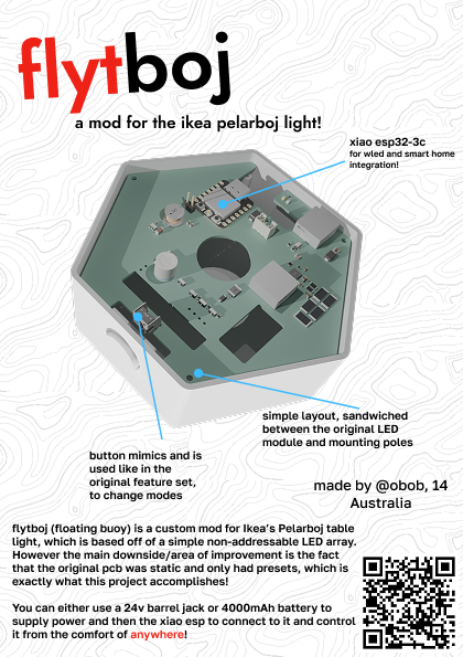
flytboj - a mod for the IKEA Pelarboj.
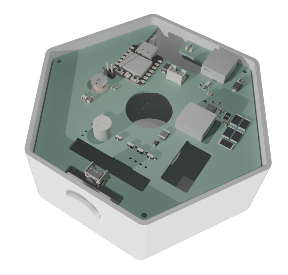
Intro and Purpose
The Ikea Pelarboj is a cool but very basic table lamp, with a single button and a tiny PCB that switches between 3 presets. I've owned a Pelarboj
for a while now and have always wanted a mod for it, to make it more capable and powerful, preferably using software like WLED and eventually smarthome integration, hence the reason
why I created this, the Flytboj (swedish for flat buoy, scroll down for more etymology :D), a board using the XIAO ESP32-3C, allowing me much finer control over the lamp in a smart
form factor that can securely fit into the existing case without any need for modifications or the destruction of it.
(in the real assembled version, the components should be facing down to allow space for the actual original LED board, but here it's the wrong side up in order to showcase the PCB so you can see more than just a blank back plane of the pcb.

Name
Pelarboj is a compound word in Swedish composed of pelare (pillar) and buoy (boj). I wanted to find a name similar to this style, and originally (or maybe not so much) thought of plattboj, flat and buoy, referncing how this mod just gets squeezed in between that LEDs and big void.
However, that name is already taken (shocker, no original thoughts exist these days 😭) in the form of disposable cell batteries, forcing me to settle on the alternative, flytboj: floating buoy ("floating" in between that layers of the interior).
OnShape
https://cad.onshape.com/documents/6a6cc990155203ee9358141d/w/edd2b1eb29a5a3bfc9bf4f54/e/d732d6e58b55189afc99dc7b?renderMode=0&uiState=6a37fa7a2eaad570a6afb0c3
PCB
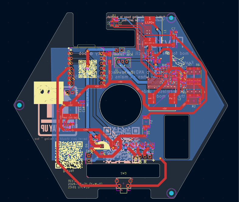
Schematic

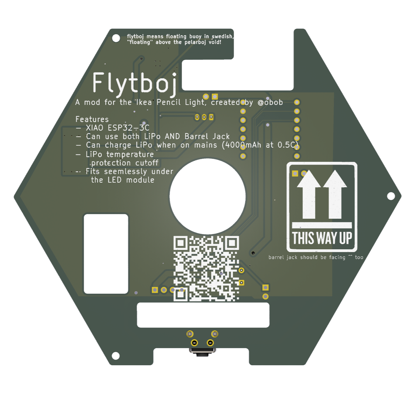
3D

Assembly
BEFOREHAND:
Flash and setup WLED on your controller.
This has a pretty straightforward assembly:
- use a phillips head screwdriver to undo the big large screw at the back of the PELARBOJ (right on top of where the barrel plug goes)
- twist and pull the top enclosure up and off
- undo the 3 smaller screws and take off the LED module
- remove the existing PCB, first by taking the bracket out and then removing the pcb from the bracket
- use a soldering iron to unsolder the pos and neg barrel jack wires (left on this image)

- do the same with the leds wires on the right. keep track of the order they are originally in.
IF USING A LiPo:
- place foam strips down to position the battery
- place the battery downon the strips
- put Flytboj into the correct place above the enclosure and plug the battery in.
Otherwise:
- Place Flytboj upside down onto the poles
- Route the barrel jack traces through the cuts in the board into a good position to solder
- Solder the barrel jack cables and the LED cables (routed through the big circle in the middle)
- Put the LED module back on
- Screw everything up
- Plug in and enjoy
BOM
[!WARNING]
The bom.csv in /production is strictly for production purposes (the one that you upload to JLCPCB's website), and doesn't contain information like price and notes (like the tables below). If you want the fully detailed boms, including an itemised component bom with prices, and an overall bom including extra parts, go to /bom. This so that JLC's tool doesn't get confused with extra fields (using /production/bom.csv) and so you can still get the information required by the fallout docs (with /bom)
Overall
PCBA Component BOM (included under PCBA in overall BOM)
| Designator | Footprint | Quantity | Value | LCSC Part # | DNP | Cost | Notes |
|---|
| C1 | 0402 | 1 | 10u | C15525 | | 0.0394 | |
| C11 | 1206 | 1 | 10u | C13585 | | 0.2836 | |
| C12 | CP_Radial_D8.0mm_P3.50mm | 1 | 100u | C2749 | | 0.1254 | extended |
| C13, C3, C4, C5, C8 | 0402 | 4 | 100n | C307331 | | 0.0760 | |
| C15, C16 | 0603 | 2 | 22u | C59461 | | 0.0944 | |
| C2 | 0603 | 1 | 100n | C14663 | | 0.0236 | |
| C4, C7 | 0805 | 2 | 22u | C45783 | | 0.4696 | |
| C6, C9 | 0805 | 2 | 10u | C440198 | | 0.8424 | |
| D1 | 0805 | 1 | GREEN | C2297 | | 0.0324 | |
| D2 | 0805 | 1 | RED | C84256 | | 0.0266 | |
| D4, D5, D6 | D_SOD-123 | 2 | D_Schottky | C8598 | | 0.1548 | |
| D3, D7 | D_SMA | 1 | D_Schottky | C22452 | | 0.1452 | |
| F1, F2 | 1812 | 2 | 5A | C20617446 | | 0.6066 | jlcpcb has no basic fuses |
| J1 | JST_PH_B3B-PH-K_1x03_P2.00mm_Vertical | 1 | Conn_01x03_Pin | C131339 | | 0.1233 | same here, no basic PH connectors |
| J2 | PinHeader_1x04_P2.54mm_Vertical | 1 | Conn_01x04 | | X | | |
| J3 | PinHeader_1x02_P2.54mm_Vertical | 1 | Conn_02x01 | | X | | |
| L1, L2 | IND-SMD_L13.5-W12.5 | 2 | 10u | C840531 | | 4.1444 | again, no basic 10uH inductors of any size |
| L3 | IND-SMD_L7.8-W7.8_SDR0805 | 1 | 4.7u | C1329416 | | 0.9314 | and here |
| Q1, Q2, Q4 | SOT-23 | 3 | AO3400A | C20917 | | 0.5028 | |
| Q3 | SOT-23 | 1 | AO3401A | C15127 | | 0.1418 | |
| R1 | 0603 | 1 | 1k | C21190 | | 0.0320 | |
| R10, R11 | 1206 | 2 | 100m | C25334 | | 0.0256 | |
| R12 | 0805 | 1 | 10k | C17414 | | 0.0068 | |
| R13, R14, R15 | 0603 | 3 | 100 | C22775 | | 0.0138 | |
| R2, R3, R5, R6, R7 | 2512 | 5 | 1 | C5127857 | | 2.8530 | extended - need to handle 2W of current |
| R4 | 0603 | 1 | 49.9k | C23184 | | 0.0036 | |
| R8 | 0603 | 1 | 100k | C25803 | | 0.0032 | |
| R9 | 0603 | 1 | 390k | C23150 | | 0.0380 | promotional extended part - no $5 fee |
| SW1 | PinHeader_1x02_P2.54mm_Vertical | 1 | SW_Push | | X | | |
| SW2 | PinHeader_1x02_P2.54mm_Vertical | 1 | SW_SPST | | X | | |
| SW3 | SW-TH_TS665ZJ | 1 | SW_Push | C557599 | | 0.1032 | extended |
| U2 | TQFN-16_L4.0-W4.0-P0.65-BL-EP | 1 | TP5100_C379389 | C379389 | | 1.0926 | extended |
| U3 | SOT-23-6 | 1 | MT3608 | C84817 | | 0.399 | extended |
| U5 | TSOT-23-6 | 1 | AP63205WU | C2071056 | | 0.8734 | extended |
| | | | | | | |
| Total | | | | | | 14.2079 | |
zine!!