2 layers40 × 107.5 mm
Utf-8-samplified
wgd-modular/utf-8-samplified
Arduino nano sample based 8-channel drum module
70 parts42
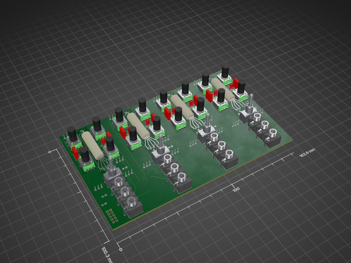
 ob1techno/valvs37
A cascading quad tube VCA module in Eurorack format.
Quad Tube VCA is an open-source printed circuit board by ob1techno, from the ob1techno/valvs repository on GitHub. It is a 2-layer board of 162.6 × 100.3 mm with 228 parts on 139 nets, routed with 1,047 tracks and 93 vias.
It is built around the TL072, LM358 and PJ301M-12. Its parts include 99 resistors, 54 capacitors, 10 ICs and 10 diodes.


A cascading quad tube VCA module in Eurorack format (3U/32hp).
Vālvs provides four gnarly tube VCAs with drive, gain, feedback, and adjustable, switchable distortion controls.
Vālvs’ outputs are daisy-chained, allowing adjacent groups of 2, 3, or all 4 channels to be mixed together.
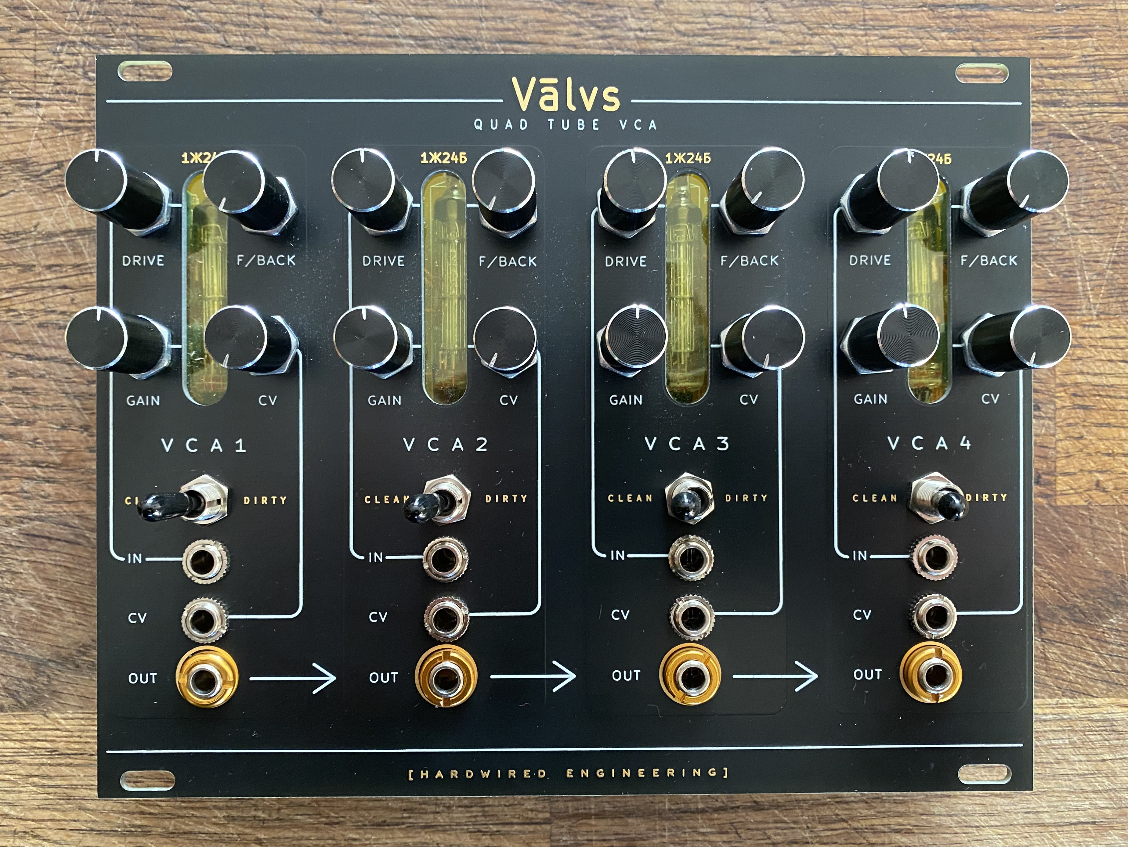
Based on/inspired by the work of Ken Stone, L-1 and Émilie Gillet, using NOS Soviet 1Ж24Б tubes; as used in the Спутник 1 satellite and Восток 1 spacecraft!
The build guide is available in the wiki.
There are no hard and fast rules here. The module is intended to be pretty flexible in terms of gain/distortion so it's very much a case of setting it up to your own taste. You could calibrate each of the 4 VCAs as closely as possible to each other to keep things consistent or you could set each up to have a different character/flavour.
Each VCA has 4 trimmers on the back of the PCB:
It's fairly important to get the CV Init trimmed correctly to avoid any audible bleed, but other than that, it's down to taste. You shoud be aware that with additional gain/distortion, there will be inevitable additional noise, so experiment to find the sweet spots.
This is inherently a pretty noisy circuit. The tubes can be a little microphonic (this can be improved a little by mounting with some foam/padding between tube and board). The LEDs in Ken Stone's original design injected some more noise as they were connected to the tube's cathode which is in the signal path. L-1's design removes the LEDs, replacing with a 1/2W resistor to ground.
I've built the circuit both ways and L-1's design is definitely less noisy. I originally thought I preferred the sound with the LEDs, but with all four VCAs mixed, the noise is too noticable, so I've gone with a resistor to ground! I've kept the LEDs to light the tubes, but these are now powered separately, away from the signal path. Even so, these are still quite noisy VCAs, though I prefer the term characterful!
I used some KiCad components/footprints that you might need to install if you want to edit the PCB files. You can find those here:
I selected parts for this module based on several factors; what I had in stock already, parts I am familiar with and like to use, availability, etc. This means it may not be the easiest module for some to build. For example, I've used 0603 passives, where I could probably have fit a larger size, or used through-hole components. I made this decision because I have a large stock of 0603 passives and I personally prefer SMT to THT. That said, I don't think this is a difficult build. I've built a few of them and it's a relatively low part count per VCA, so quite quick to put together. The surface mount components used also make this suitable for SMD fabrication/assembly services, which I have used successfully on my latest builds.
The construction should all be self explanatory as it's just a single board. Parts go on the side where their silkscreen is (although if you used particularly tall film box caps, you might need to move them to the back).
There's also the option of mounting the trimmers for the clean/dirty distortion on the front of the PCB and drilling holes so they're adjustable from the front, if you like that sort of thing.
It's worth using some heatshrink on the tube legs for peace of mind, though not strictly necessary, and I like to use some acetate sheet to fill the windows in case of dust, stray cables, etc.
There are some build photos in the wiki.
I am not an electronic engineer. I am a musician/programmer with a keen interest in synthesis and electronics. I am entirely self-taught; this was my first project using KiCad and I'm sure I have made many mistakes.
I have tried to ensure that this works before publishing my work, but this is presented as-is and with no guarantees or acceptance of responsibility on my part. I'd welcome any feedback and I am interested in improving the design; please use the issues section or submit a pull request.
I also make no promises to support this project, but do get in touch and I'll help if I can.
| Qty | Value | Footprint | References |
|---|---|---|---|
| 46 | 100k | Resistor_SMD:R_0603_1608Metric | R3, R4, R14, R17, R21, R23, R26, R27, R28, R30, R31, R32, R34, R39, R41, R45 +30 |
| 24 | 100nf | Capacitor_SMD:C_0603_1608Metric | C10, C11, C12, C13, C14, C15, C16, C22, C23, C26, C27, C28, C36, C37, C38, C39 +8 |
| 16 | 47pf | Capacitor_SMD:C_0603_1608Metric | C3, C4, C8, C9, C17, C18, C24, C25, C29, C30, C34, C35, C43, C44, C48, C49 |
| 12 | A100k | Eurocad:Alpha9mmPot | POT_FEEDBACK1, POT_FEEDBACK2, POT_FEEDBACK3, POT_FEEDBACK4, POT_GAIN1, POT_GAIN2, POT_GAIN3, POT_GAIN4, POT_IN_DRIVE1, POT_IN_DRIVE2, POT_IN_DRIVE3, POT_IN_DRIVE4 |
| 12 | PJ301M-12 | Eurocad:PJ301M-12 | J_CV_IN1, J_CV_IN2, J_CV_IN3, J_CV_IN4, J_IN1, J_IN2, J_IN3, J_IN4, J_OUT1, J_OUT2, J_OUT3, J_OUT4 |
| 8 | 100k | Potentiometer_THT:Potentiometer_Bourns_3296W_Vertical | TRIM_CLEAN1, TRIM_CLEAN2, TRIM_CLEAN3, TRIM_CLEAN4, TRIM_CV_INIT1, TRIM_CV_INIT2, TRIM_CV_INIT3, TRIM_CV_INIT4 |
| 8 | 1k2 | Resistor_SMD:R_0603_1608Metric | R15, R16, R38, R40, R63, R66, R87, R89 |
| 8 | 220k | Resistor_SMD:R_0603_1608Metric | R18, R19, R42, R43, R65, R67, R90, R91 |
| 8 | 33k | Resistor_SMD:R_0603_1608Metric | R2, R12, R25, R36, R49, R60, R73, R84 |
| 8 | 470nf | Capacitor_THT:C_Rect_L7.2mm_W2.5mm_P5.00mm_FKS2_FKP2_MKS2_MKP2 | C5, C6, C19, C20, C31, C32, C45, C46 |
| 8 | LED | LED_THT:LED_D3.0mm | D3, D4, D5, D6, D7, D8, D9, D10 |
| 6 | TL072 | Package_SO:SOIC-8_3.9x4.9mm_P1.27mm | IC1, IC2, IC4, IC6, IC7, IC9 |
| 4 | 10k | Resistor_SMD:R_0603_1608Metric | R22, R46, R70, R94 |
| 4 | 1J24B | Valve:Valve_Mini_Pentode_1j24b | V1, V2, V3, V4 |
| 4 | 1M | Potentiometer_THT:Potentiometer_Bourns_3296W_Vertical | TRIM_DIST1, TRIM_DIST2, TRIM_DIST3, TRIM_DIST4 |
| 4 | 1k | Resistor_SMD:R_0603_1608Metric | R1, R24, R48, R72 |
| 4 | 20k | Potentiometer_THT:Potentiometer_Bourns_3296W_Vertical | TRIM_PLATE1, TRIM_PLATE2, TRIM_PLATE3, TRIM_PLATE4 |
| 4 | 2k2 | Resistor_SMD:R_0603_1608Metric | R11, R35, R59, R83 |
| 4 | 330R | Resistor_SMD:R_0603_1608Metric | R10, R33, R57, R82 |
| 4 | 47uf | Capacitor_THT:CP_Radial_D5.0mm_P2.50mm | C7, C21, C33, C47 |
| 4 | 51k | Resistor_SMD:R_0603_1608Metric | R20, R44, R68, R92 |
| 4 | 750R | Resistor_SMD:R_1210_3225Metric | R13, R37, R61, R85 |
| 4 | 8k2 | Resistor_SMD:R_0603_1608Metric | R6, R29, R53, R77 |
| 4 | B100k | Eurocad:Alpha9mmPot | POT_CV_LEVEL1, POT_CV_LEVEL2, POT_CV_LEVEL3, POT_CV_LEVEL4 |
| 4 | LM358 | Package_SO:SOIC-8_3.9x4.9mm_P1.27mm | IC3, IC5, IC8, IC10 |
| 4 | SW_SPDT | 100SP1T1B4M2QE:SW_100SP1T1B4M2QE | SW_DIST1, SW_DIST2, SW_DIST3, SW_DIST4 |
| 2 | 10uf | Capacitor_THT:CP_Radial_D5.0mm_P2.50mm | C1, C2 |
| 2 | 1N5819 | Diode_SMD:D_SOD-123 | D1, D2 |
| 2 | Ferrite | Resistor_SMD:R_0603_1608Metric | FB1, FB2 |
| 1 | 100R | Resistor_SMD:R_0603_1608Metric | R7 |
| 1 | EURO_PWR_2x5 | Connector_PinHeader_2.54mm:PinHeader_2x05_P2.54mm_Vertical | JP1 |
It measures 162.6 × 100.3 mm and has 2 copper layers, 1.6 mm thick.
228 parts, built around the TL072, LM358 and PJ301M-12. The full list of its parts is on this page, with links to each part's symbol and footprint where PCBKit's library has them.
From the ob1techno/valvs repository on GitHub, at the commit this page was made from: the board is KiCad/Quad Tube VCA.kicad_pcb. PCBKit opens the board in the browser, with nothing to install.
Its repository states no licence, so its author keeps all rights: ask ob1techno before reusing the design.
wgd-modular/utf-8-samplified
Arduino nano sample based 8-channel drum module


JordanAceto/modulation_source
Eurorack compatible pcb with sine/square VCLFO, white and pink noise, and sample & hold

JordanAceto/Filter_Carrier_Board
PCB carrier board for various VCF plug-in boards


JordanAceto/SSM2164-SVF
State variable filter with audio and super low frequency modes

Thorinair/Avalon-Harmonics
A collection of Avalon Harmonics branded synthesizer modules.

punkfab/pcb-corpus
235 real KiCad boards from open-source hardware repositories, prepared as a placement and routing benchmark