2 layers43.9 × 27.7 mm

 nunosmash/SPIDER
BLE MIDI Gateway / Professional Wireless MIDI Hub & Bridge System
SPIDER Gateway is an open-source printed circuit board by nunosmash, from the nunosmash/SPIDER repository on GitHub, published under the Apache-2.0 licence. It is a 2-layer board of 50 × 35 mm with 19 parts on 44 nets, routed with 207 tracks and 26 vias.
Its parts include 9 resistors, 3 ICs, 3 connectors, 1 capacitor and 1 switch. It belongs with the audio and music boards of this library.
BLE MIDI gateway — bridge Bluetooth LE MIDI controllers to USB MIDI and DIN MIDI, with up to three simultaneous BLE devices, fixed slot routing, and HOST / CLIENT roles for stage and DAWless setups.
Part of the Ash Sound Works custom tools for live and studio — by sound artist and producer Ash (Ahn Sunghoon) · GitHub / Manual
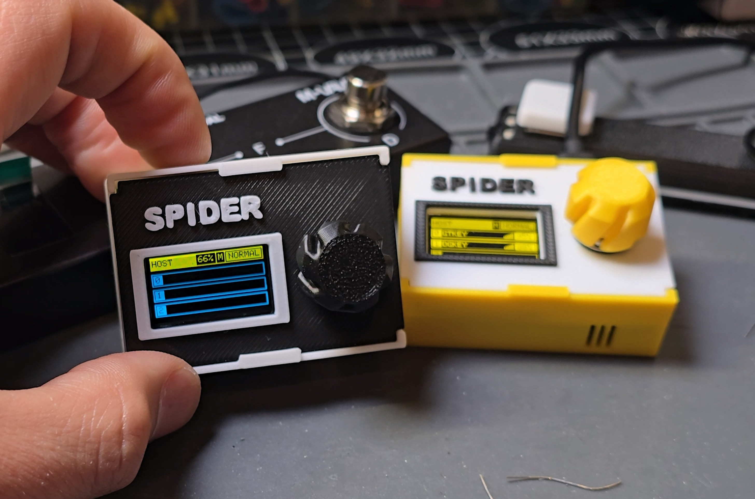
Running cables across a crowded pedalboard or needing remote control for other players is awkward. SPIDER was built around BLE MIDI on a dedicated nRF52840 radio (e.g. nice!nano class hardware): low power, battery-friendly, and focused on wireless MIDI rather than sharing the stack with a desktop OS BLE stack.
| Role | Behavior (summary) |
|---|---|
| Slot 0 (master) | USB ↔ BLE ↔ DIN MIDI |
| Slots 1–2 | USB ↔ BLE |
| Port pinning | Each slot stores MAC + name so devices always map to the same slot regardless of power-on order |
Tip: Keep 3+ bars within ~10 m for dependable live use.
Preferences → Link / Tempo / MIDI
| Slot | USB MIDI port |
|---|---|
| SLOT 1 | Port 1 |
| SLOT 2 | Port 2 |
| SLOT 3 | Port 3 |
BLE adds variable delay; align with audio using Track Delay like any MIDI path. Many setups start around −10 ms ~ −20 ms (often −18 ms) and refine by recording MIDI out + external audio and matching to the grid.
(Exact filename and format follow your published release notes.)
Depending on branch or release:
Full wiring, menus, and edge cases: spider-manual.html in the Ash Sound Works bundle.
| Category | Component Description | Qty |
|---|---|---|
| MCU | nRF52840 (nice!nano v2.0 SuperMini) | 1 |
| Display | 0.91" OLED Module (128x64) | 1 |
| Optocoupler | 6N138 High-Speed Optocoupler | 1 |
| Diode | 1N4001 Rectifier Diode | 1 |
| Capacitor | 100μF Electrolytic Capacitor | 1 |
| Input | EC11 Rotary Encoder w/ Push Switch | 1 |
| Connectors | PJ-320A 3.5mm Stereo Jack | 2 |
| Power | SS-12F23 Slide Switch | 1 |
| Resistors | 220Ω (x2), 330Ω (x2), 150Ω, 1kΩ, 4.7kΩ, 10Ω, 30Ω | 9 |
spider-manual.htmlSee the LICENSE file in the repository root.
| Qty | Value | Footprint | References |
|---|---|---|---|
| 2 | 220 | Resistor_THT:R_Axial_DIN0204_L3.6mm_D1.6mm_P7.62mm_Horizontal | R4, R8 |
| 2 | 330 | Resistor_THT:R_Axial_DIN0204_L3.6mm_D1.6mm_P7.62mm_Horizontal | R13, R14 |
| 1 | 10 | Resistor_THT:R_Axial_DIN0204_L3.6mm_D1.6mm_P7.62mm_Horizontal | R19 |
| 1 | 100uF | Capacitor_THT:CP_Radial_D6.3mm_P2.50mm | C1 |
| 1 | 150 | Resistor_THT:R_Axial_DIN0204_L3.6mm_D1.6mm_P7.62mm_Horizontal | R5 |
| 1 | 1k | Resistor_THT:R_Axial_DIN0204_L3.6mm_D1.6mm_P7.62mm_Horizontal | R9 |
| 1 | 1n4001 | Diode_THT:D_DO-35_SOD27_P7.62mm_Horizontal | 1n4001 |
| 1 | 30 | Resistor_THT:R_Axial_DIN0204_L3.6mm_D1.6mm_P7.62mm_Horizontal | R20 |
| 1 | 4.7k | Resistor_THT:R_Axial_DIN0204_L3.6mm_D1.6mm_P7.62mm_Horizontal | R10 |
| 1 | 6N138 | Package_DIP:DIP-8_W7.62mm | U2 |
| 1 | BATTERY | Connector_PinHeader_2.54mm:PinHeader_1x02_P2.54mm_Vertical | J1 |
| 1 | EC11 | Rotary_Encoder:RotaryEncoder_Alps_EC11E-Switch_Vertical_H20mm | Enc5 |
| 1 | MIDI IN ◁ | [Libraries]:PJ-320A | J2 |
| 1 | MIDI OUT | [Libraries]:PJ-320A | J3 |
| 1 | OLED-I2C | [Libraries]:128x64OLED | U3 |
| 1 | SW_SPDT | KiCadCustomLibs-master:SS-12F23 | SW1 |
| 1 | nFR52840 nice! nano v2 | SuperMini NRF52840:SuperMini NRF52840 | U1 |
It measures 50 × 35 mm and has 2 copper layers, 1.6 mm thick.
19 parts. The full list of its parts is on this page, with links to each part's symbol and footprint where PCBKit's library has them.
From the nunosmash/SPIDER repository on GitHub, at the commit this page was made from: the board is Kicad/SPIDER Gateway.kicad_pcb and its schematic Kicad/SPIDER Gateway.kicad_sch. PCBKit opens the board in the browser, with nothing to install.
Its repository publishes it under the Apache-2.0 licence: you may reuse it on that licence's terms (keep the author's notice, and for a copyleft licence share your changes alike).

hackclub/OnBoard
💡 Join 1,000 teenagers and make your first PCB with a $100 grant!

polpo/picogus
Emulation of ISA sound cards and CD-ROM on Raspberry Pi Pico (GUS, SB/Adlib, MPU-401, Tandy, CMS, Panasonic CD-ROM) with USB mouse/joystick support


nkitanov/iaq_board
IAQ Board is a DIY (Do-It-Yourself) device for measuring internal air quality


Ardumower/ardumower
Develop an open source robotic lawn mower (HW+SW reference platform)

zmaker/arduino_cookbook
gli sketch del nuovo progetto Arduino Cookbook e dei video di YouTube