2 layers86.1 × 85.9 mm
 ntnunk/led_cube
8x8x8 LED Cube
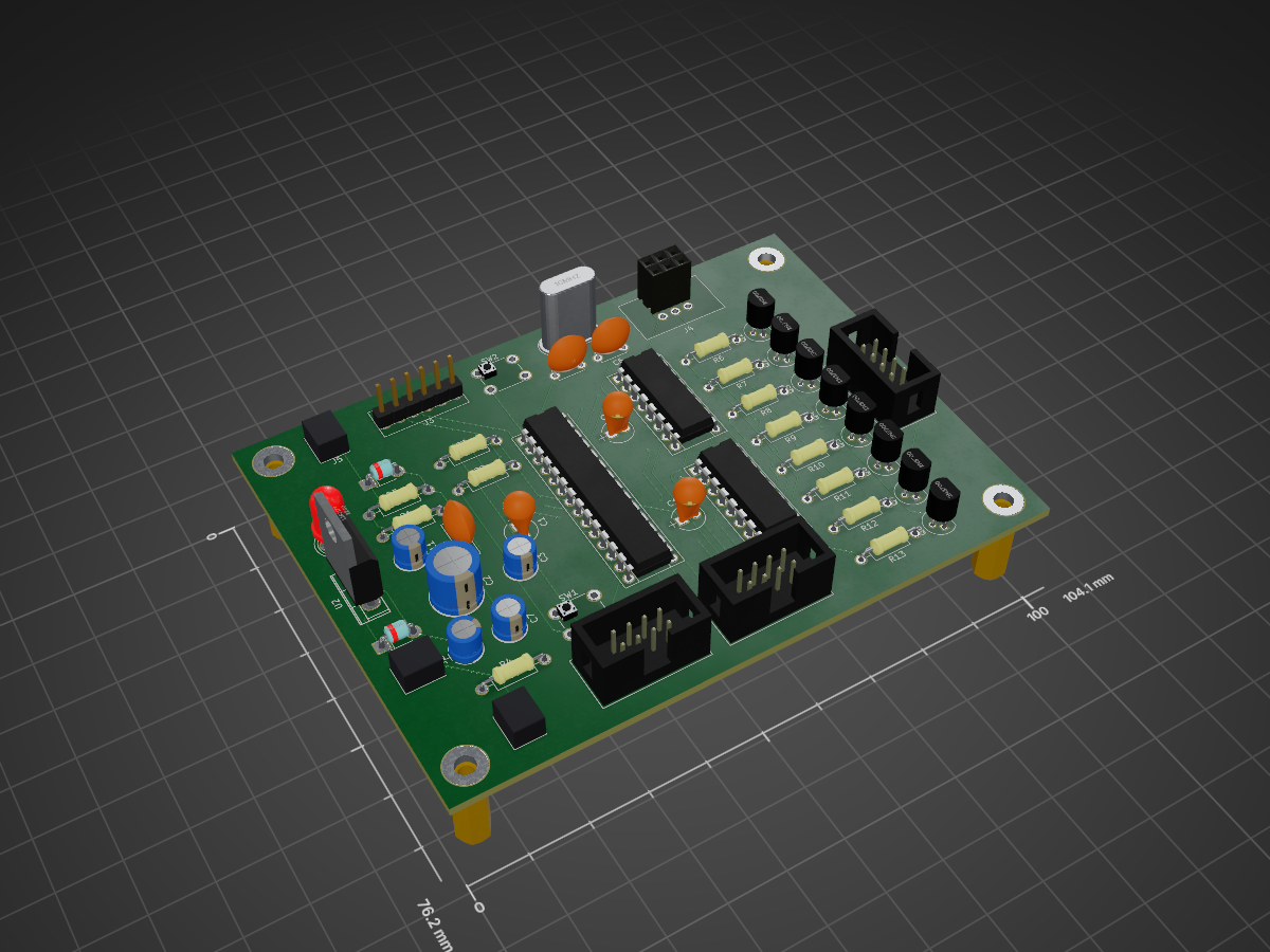
Controller is an open-source printed circuit board by ntnunk, from the ntnunk/led_cube repository on GitHub. It is a 2-layer board of 104.1 × 76.2 mm with 54 parts on 73 nets, routed with 523 tracks and 37 vias.
It is built around the ATMEGA328-PU, 74HC238D and LM317T. Its parts include 13 resistors, 11 capacitors, 8 transistors, 8 connectors and 4 ICs. It belongs with the AVR (ATmega, ATtiny) boards of this library.


My 8x8x8 LED Cube project. This repository will eventually contain both code and circuit schematics. Schematics and printed circuit boards designed in Kicad.
The cube is composed of eight layers of eight LEDs per side, or sixty-four LEDs per layer. The cube relies upon persistance of vision, much like a flourescent light, which means there is never actually more than one LED layer active at a time. Because the controller cycles through the layers so quickly it fools the human eye and appears as though the cube is lit continuously.
The LED cube itself is constructed of layers and columns of LEDs. The anodes every LED in a given column are connected together while the cathodes of every LED in a given layer are connected together. Individual LEDs can be turned on by having power applied to the vertical column the LED is part of and then having the layer it's part of switched to ground.
The controller for this project is essentially a simplified Arduino Duemilanove with an ATMEL ATMEGA328P processor. A 74HC238 3-to-8 decoder is used to select one of eight general purpose NPN transistors. The eight transistors have the base connected to an output pin of the decoder, the emitter to ground, and the collector to the cathodes of the LEDs in the transistor's associated layer. Since the cathodes of all LEDs on a given layer are connected together, turning on one of the layer enable transistors connects the cathodes of that layer's LEDs to ground, causing any LEDs in the layer with power applied to their anodes to turn on.
The second major section is the LED driver. Since the controller doesn't have enough GPIO pins to control the number of LEDs required, another 74HC238 3-to-8 decoder is used in conjunction with eight 74HC595N serial-in, parallel-out 8-bit shift registers to control the 64 LEDs on a layer. The shift registers could be connected in serial, removing the need for the extra decoder, but that would require 64 clock cycles per layer change to push all the LED enable bits into the 8 daisy-chained shift registers. Instead, the shift registers are connected in parallel with each shift register IC (integrated circuit) controlling an individual LED on each row of the layer. So, for example, the first 8-bit shift register controls the first LED in all eight of the rows on a layer.
The processor enables the three input lines on the decoder chip based on which LEDs on the first row are indicated by the control program. The decoder sets the 8 output lines based on the 3 input lines. The 8 output lines are sent to the serial in of each shift register, the processor toggles the serial clock to move the shift registers one position, then the process repeats until all 8 output lines of all 8 shift registers are set as desired for the layer.
The shift register output lines drive the anodes of all the LEDs on the layer. Once the processor switches the cathodes of the layer to ground via the layer enable transistors as described above, the enabled LEDs in the layer will light up and stay lit until the processor sets up and enables the next layer in the sequence.
| Qty | Value | Footprint | References |
|---|---|---|---|
| 9 | 330 | Resistors_THT:R_Axial_DIN0207_L6.3mm_D2.5mm_P10.16mm_Horizontal | R5, R6, R7, R8, R9, R10, R11, R12, R13 |
| 8 | 2N3700 | TO_SOT_Packages_THT:TO-92_Molded_Narrow | Q1, Q2, Q3, Q4, Q5, Q6, Q7, Q8 |
| 3 | 0.1uF | Capacitors_THT:CP_Radial_Tantal_D5.0mm_P2.50mm | C1, C9, C10 |
| 3 | 10uF | Capacitors_THT:CP_Radial_D5.0mm_P2.00mm | C3, C7, C11 |
| 2 | 10k | Resistors_THT:R_Axial_DIN0207_L6.3mm_D2.5mm_P10.16mm_Horizontal | R2, R3 |
| 2 | 1K | Resistors_THT:R_Axial_DIN0207_L6.3mm_D2.5mm_P10.16mm_Horizontal | R1, R4 |
| 2 | 1N4001 | Diodes_THT:D_T-1_P5.08mm_Horizontal | D2, D3 |
| 2 | 22pF | Capacitors_THT:C_Disc_D4.7mm_W2.5mm_P5.00mm | C5, C6 |
| 2 | 74HC238 | Housings_DIP:DIP-16_W7.62mm_Socket | U3, U4 |
| 1 | +12V_IN | Connectors:PINHEAD1-2 | J1 |
| 1 | +5V_OUT | Connectors:PINHEAD1-2 | J5 |
| 1 | 0.1uF | Capacitors_THT:CP_Radial_D5.0mm_P2.00mm | C8 |
| 1 | 0.1uF | Capacitors_THT:C_Disc_D8.0mm_W2.5mm_P5.00mm | C4 |
| 1 | 1000uF | Capacitors_THT:CP_Radial_D8.0mm_P3.50mm | C2 |
| 1 | 16MHz | Crystals:Crystal_HC49-U_Vertical | Y1 |
| 1 | ATMEGA328-PU | Housings_DIP:DIP-28_W7.62mm_Socket | U1 |
| 1 | DBG_SW | Buttons_Switches_THT:SW_PUSH_6mm | SW1 |
| 1 | DRV_SIG1 | Connectors:IDC_Header_Straight_8pins | J6 |
| 1 | DRV_SIG2 | Connectors:IDC_Header_Straight_8pins | J7 |
| 1 | LAYER_EN | Connectors:IDC_Header_Straight_8pins | J8 |
| 1 | LED | LEDs:LED_D5.0mm | D1 |
| 1 | LM317T | Power_Integrations:TO-220 | U2 |
| 1 | PROG | Connectors:IDC_Header_Straight_6pins | J4 |
| 1 | PWR_SW | Connectors:PINHEAD1-2 | J2 |
| 1 | RESET_SW | Buttons_Switches_THT:SW_PUSH_6mm | SW2 |
| 1 | SERIAL | Connectors:PINHEAD1-6 | J3 |
The 50 most common of 54 parts.
It measures 104.1 × 76.2 mm and has 2 copper layers, 1.6 mm thick.
54 parts, built around the ATMEGA328-PU, 74HC238D and LM317T. The full list of its parts is on this page, with links to each part's symbol and footprint where PCBKit's library has them.
From the ntnunk/led_cube repository on GitHub, at the commit this page was made from: the board is PCBs/controller/controller.kicad_pcb. PCBKit opens the board in the browser, with nothing to install.
Its repository states no licence, so its author keeps all rights: ask ntnunk before reusing the design.

Ulf-vom-Mond/ofen_v2
I am building a high temperature oven which I want to go up to 1300 °C. It will be used for melting glass and metals and doing pottery.


john0312/hitcon-pcb-badge
execute fw/merge.py to merge STM32CubeIDE generated main.c with user code in main.cc into main.cc.

KipJM/blackmacro-hardware
An open source, smaller, more configurable, and more capabable video editing keyboard based on the raspberry Pi Pico 2W.


Edgeworth/memepu
cmake -DUSEAFL=yes -DCMAKEBUILDTYPE=Release $PFX/verymeme AFLSKIPCPUFREQ=yes AFLPRELOAD=/usr/local/lib/afl/libdislocator.so \ afl-fuzz -m 1024M -i $PFX/verymeme/testdata/memelang/parsing -o memelangfuzz \ -x…