4 layers52 × 76 mm
Isospi transceiver
npgo22/APRL-Electrical-New
To use the board templates, set KICADUSERTEMPLATEDIR by:
85 parts

 npgo22/APRL-Electrical-New
To use the board templates, set KICADUSERTEMPLATEDIR by:
Valvedrivers is an open-source printed circuit board by npgo22, from the npgo22/APRL-Electrical-New repository on GitHub. It is a 4-layer board of 85 × 76 mm with 145 parts on 207 nets, routed with 711 tracks and 512 vias.
It is built around the LAN8742AI-CZ-TR, TJA1462ATK/0Z and IPS4140HQ, with the LTV-816S-TA1-C, SN74CBTLV3245APW and AP2112K-3.3TRG1 among its other parts. Its parts include 48 capacitors, 47 resistors, 21 connectors, 11 ICs and 6 diodes. It belongs with the STM32 boards of this library.


APRL KiCad Projects.
First, clone the repository with git clone. GitHub has a button which gives you the command to do this.
Then, you will have to use git lfs pull to get all the 3D models and images.
To use the board templates, set KICAD_USER_TEMPLATE_DIR by:
KICAD_USER_TEMPLATE_DIR to wherever you cloned this repo + /kicadlibs/templates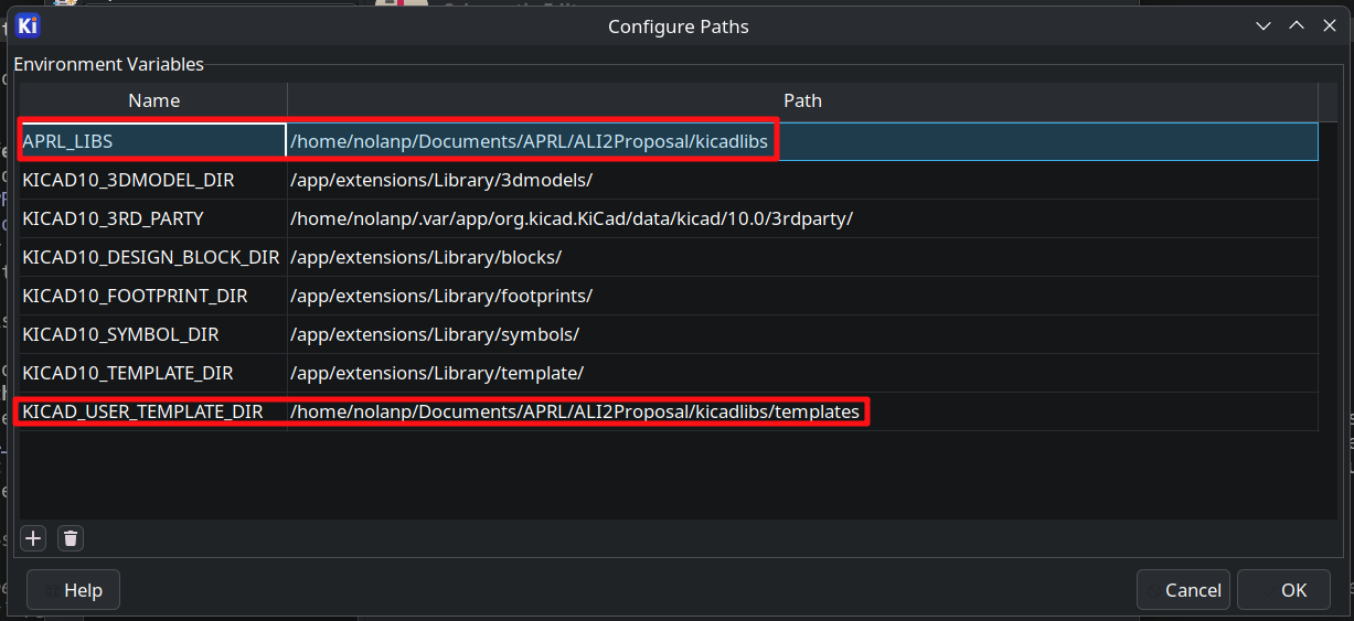
The exigence of this endeavour is twofold:
The ALI itself can continue to be used for years to come and this reworking of the electronics will not impact it at all. This is going to be its own separate electrical box altogether. The ALI has the following additional limitations, too:
Therefore, we have started work on a true replacement. Each of the modules serve a specific task, and are hooked to a common ethernet-based network which is far more performant than the original layout while simultaneously being easier to understand and expand. If you want more I/O, you can just simply add another board within a few minutes. Likewise, by opting for cutouts in the enclosure over dedicated port holes, it is also far easier to revise significant parts of the design without needing to drill through steel.
This system is +5V and +24V only, with +3.3V regulated on each board.
On the ground station, we are planning to use Ethernet instead of CANBUS. While this means our session protocol will not be tested in a real-world hotfire scenario, it does mean we can fully exploit each of the features offered by ethernet:
Each of the modules will have a CAN transceiver anyway available for testing.
kicadlibs/                                 Shared KiCad libraries
  aprl/                                      APRL's custom symbols and footprints
  aprl/*-noct.pretty                         "aprl/" but without courtyards
  vendor/                                    Third-party libs
  models/                                    3D models KiCad does not ship
  APRL_*_Sheet.kicad_wks                     Drawing sheets
  jlcpcb-4layer.kicad_dru                    Canonical JLCPCB design rules
.github/scripts                              Helper scripts runnable via Just and GH actions


ali/2/                                     New ALI electronics
ali/1/                                     Old ALI electronics
ophio/                                     DPF Vehicle Boards
misc/ Other endeavorsYou may use AI to research topics and to write one-off scripts which do minor modifications and automate tedious, minor tasks. For example, if you need to color in a bunch of models feel free to.
What you cannot use it for is end to end electrical design, layout, and documentation. Documents should be written by people, and a schematic falls under this category. Likewise, using AI to automate layout is A. ineffective because it does not generate high-quality layouts and B. defeats the purpose of this club, which is to learn about electronics.
| Qty | Value | Footprint | References |
|---|---|---|---|
| 35 | 10k | APRL_Passive:R_0603 | R10, R11, R12, R18, R20, R24, R25, R26, R27, R28, R29, R30, R31, R32, R33, R34 +19 |
| 16 | 100nF | APRL_Passive:C_0603 | C2, C3, C4, C5, C6, C7, C19, C20, C21, C27, C28, C30, C31, C37, C43, C44 |
| 12 | 10nF | APRL_Passive:C_0603 | C32, C33, C34, C35, C38, C39, C40, C41, C45, C46, C47, C48 |
| 12 | Conn_01x02 | APRL_Connector_Molex:Molex_CLIK-Mate_503159-0201_1x02-1MP_P1.50mm_Vertical | J10, J11, J12, J13, J14, J15, J16, J17, J18, J19, J20, J21 |
| 6 | 22uF | APRL_Passive:C_0805 | C12, C13, C14, C15, C16, C17 |
| 6 | LED | APRL_Passive:LED_0603 | D1, D2, D3, D4, D5, D6 |
| 4 | 15pF | APRL_Passive:C_0603 | C8, C9, C25, C26 |
| 4 | 47R | APRL_Passive:R_0603 | R14, R15, R16, R17 |
| 4 | MountingHole | APRL_Misc:MountingHole_3.2mm_M3 | H1, H2, H3, H4 |
| 3 | 1uF | APRL_Passive:C_0603 | C1, C18, C22 |
| 3 | 47uF | APRL_Passive:KEMET MU VIB | C29, C36, C42 |
| 3 | IPS4140HQ | APRL_Package:QFN-48_EP_9.01x7.01_Pitch0.5mm | U8, U9, U11 |
| 3 | Screw_Terminal_01x02 | APRL_Connector:PhoenixContact_MSTBV_2,5_2-GF-5,08_1x02_P5.08mm_Vertical_ThreadedFlange_MountHole | J4, J5, J6 |
| 2 | 2.2uF | APRL_Passive:C_0603 | C10, C11 |
| 2 | 25 MHz | APRL_Passive:3225-4P-L | Y1, Y2 |
| 2 | 330R | APRL_Passive:R_0603 | R21, R22 |
| 2 | 5.1k | APRL_Passive:R_0603 | R1, R2 |
| 2 | 500mA | APRL_Passive:Fuse_0805_2012Metric | F1, F3 |
| 2 | Conn_01x05 | APRL_Connector_Molex:Molex_CLIK-Mate_503159-0501_1x05-1MP_P1.50mm_Vertical | J2, J7 |
| 2 | LTV-816S | APRL_Package:4-SMD | U2, U4 |
| 2 | SN74CBTLV3245A | APRL_Package:TSSOP-20_4.4x6.5mm_P0.65mm | U7, U10 |
| 1 | 1.5k | APRL_Passive:R_0603 | R13 |
| 1 | 100k | APRL_Passive:R_0603 | R3 |
| 1 | 100mA | APRL_Passive:Fuse_0805_2012Metric | F4 |
| 1 | 10A hold | APRL_Connector:FuseHolder_Blade_ATO_Littelfuse_FLR_178.6165 | F2 |
| 1 | 12.1k | APRL_Passive:R_0603 | R19 |
| 1 | 120R | APRL_Passive:R_0603 | R23 |
| 1 | 220nF | APRL_Passive:C_0603 | C24 |
| 1 | 470pF | APRL_Passive:C_0603 | C23 |
| 1 | AP2112K-3.3 | Package_TO_SOT_SMD:SOT-23-5 | U3 |
| 1 | Conn_01x03 | APRL_Connector_Molex:Molex_CLIK-Mate_503159-0301_1x03-1MP_P1.50mm_Vertical | J9 |
| 1 | Conn_02x01 | Connector_PinHeader_2.54mm:PinHeader_1x02_P2.54mm_Vertical | J1 |
| 1 | LAN8742AI | APRL_Package_QFN:VQFN-24-1EP_4x4mm_P0.5mm_EP2.5x2.5mm_ThermalVias | U5 |
| 1 | SKRPANE010 | APRL_Module:SKRPANE010 | SW1 |
| 1 | STM32H563RIV6 | APRL_Package_QFN:QFN-68-1EP_8x8mm_P0.4mm_EP6.4x6.4mm | U1 |
| 1 | TJA1462ATK | APRL_Package_QFN:HVSON-8-1EP_3x3mm_P0.65mm_EP1.6x2.4mm_ThermalVias | U6 |
| 1 | USB_C_Receptacle_USB2.0_16P | APRL_Connector:USB_C_Receptacle_G-Switch_GT-USB-7051x | J3 |
| 1 | Vertical Ethernet | APRL_Connector:RJ45_Hanrun_HY951180A_Vertical | J8 |
The 144 most common of 145 parts.
npgo22/APRL-Electrical-New
To use the board templates, set KICADUSERTEMPLATEDIR by:

npgo22/APRL-Electrical-New
To use the board templates, set KICADUSERTEMPLATEDIR by:


SlimeVR/SlimeVR-Morphocharger
SlimeVR Official charger design for butterfly trackers

o7-machinehum/wifiwart
Linux SBC featuring two wifi radios, masquerading as a USB charger.

clydeshaffer/gametank
design files for the gametank hardware implementation


It measures 85 × 76 mm and has 4 copper layers, 1.6 mm thick.
145 parts, built around the LAN8742AI-CZ-TR, TJA1462ATK/0Z, IPS4140HQ and LTV-816S-TA1-C. The full list of its parts is on this page, with links to each part's symbol and footprint where PCBKit's library has them.
From the npgo22/APRL-Electrical-New repository on GitHub, at the commit this page was made from: the board is ali/2/valvedrivers/valvedrivers.kicad_pcb and its schematic ali/1/ThermoBoard/ThermoBoard.kicad_sch. PCBKit opens the board in the browser, with nothing to install.
Its repository states no licence, so its author keeps all rights: ask npgo22 before reusing the design.