
2 layers327.9 × 139 mm
Coco2
baldengineer/bit-preserve
Project for capturing vintage, classic, aka old computer schematics in KiCad.
147 parts446

 notyourcto/led-chaser2
designed pcb for led-chaser
Led chaser is an open-source printed circuit board by notyourcto, from the notyourcto/led-chaser repository on GitHub. It is a 2-layer board of 87 × 38.9 mm with 30 parts on 28 nets, routed with 332 tracks and 0 vias.
It is built around the NE555P. Its parts include 12 resistors, 11 diodes, 3 capacitors and 2 ICs.
this project is abt me trying pcb design after attending build guild by hackclub. we were building this led chaser circuit on breadboard during the event itself and after initial protyping i started working on design.
it uses ne555 timer to generate clock and cd4017 to light leds one by one.
ne555 generates pulses → those pulses go into cd4017 → cd4017 shifts output across pins → each pin drives one led
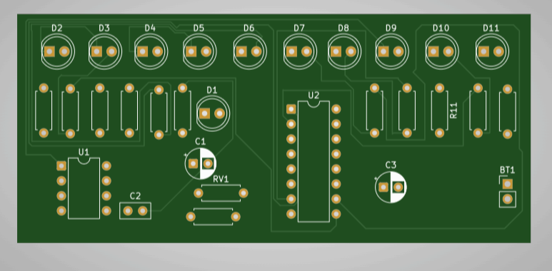
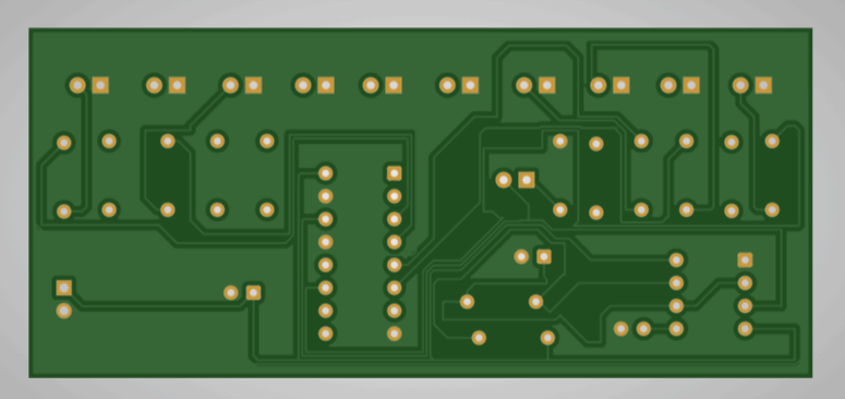
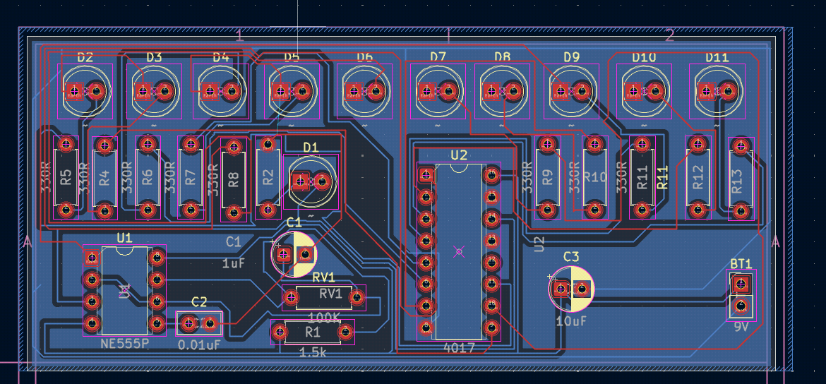
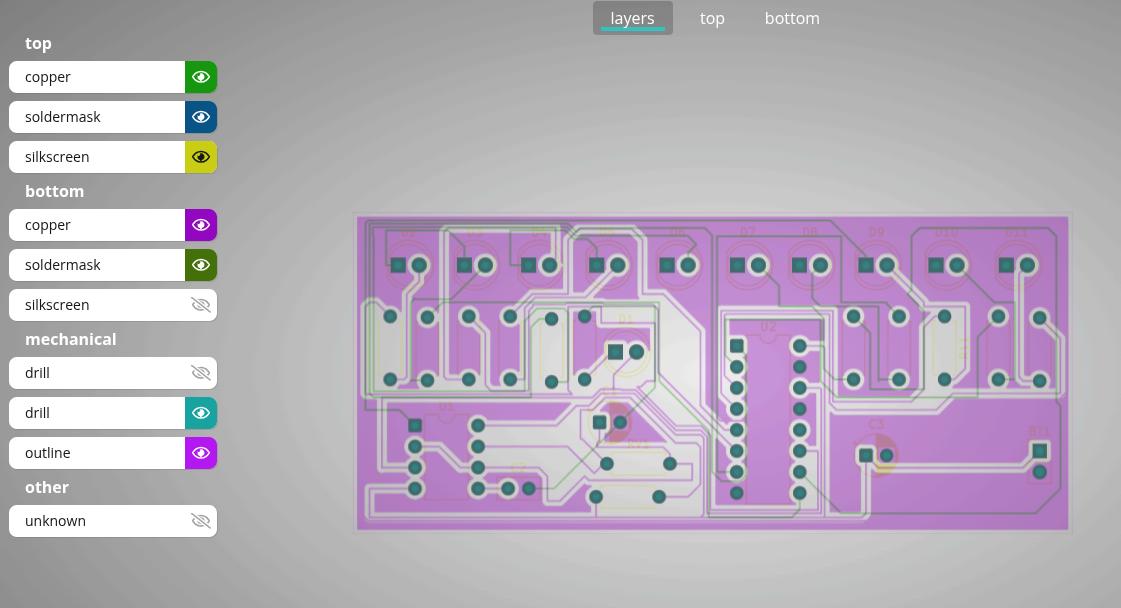
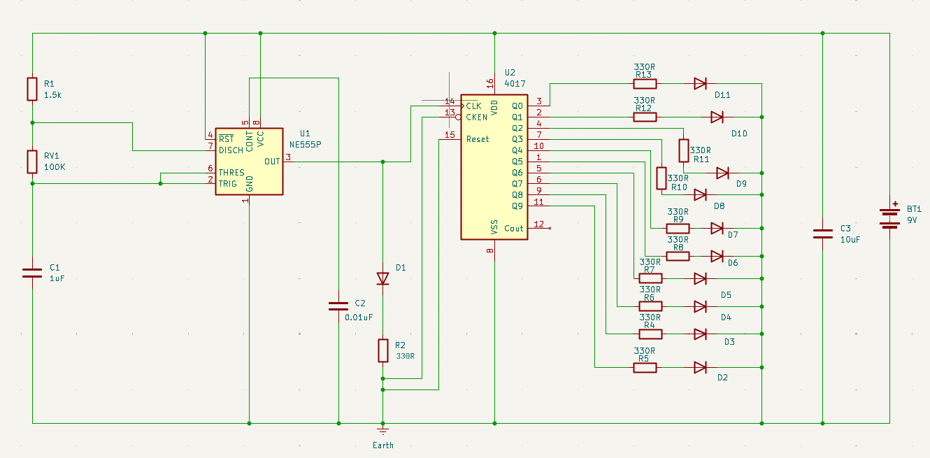
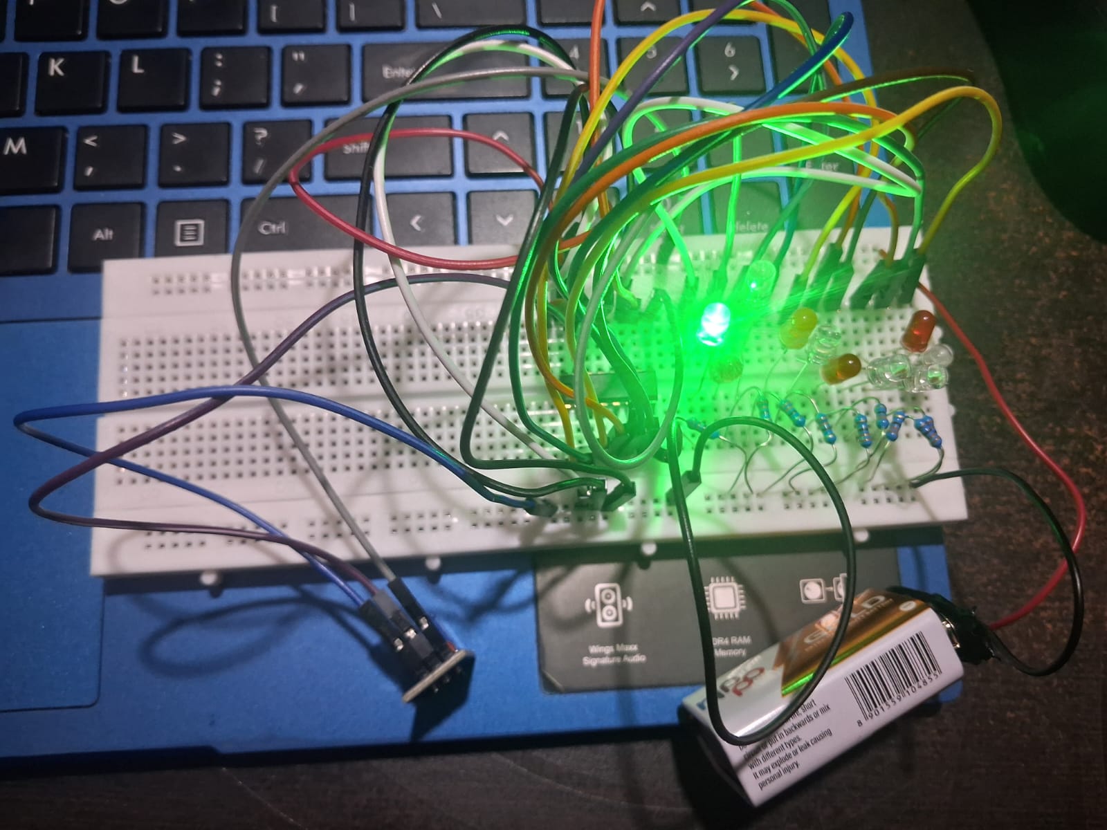
this was mostly exploration and learning. not optimized but works and ready to manufacture.
| Qty | Value | Footprint | References |
|---|---|---|---|
| 11 | 330R | Resistor_THT:R_Axial_DIN0207_L6.3mm_D2.5mm_P7.62mm_Horizontal | R2, R4, R5, R6, R7, R8, R9, R10, R11, R12, R13 |
| 11 | ~ | LED_THT:LED_D5.0mm | D1, D2, D3, D4, D5, D6, D7, D8, D9, D10, D11 |
| 1 | 0.01uF | Capacitor_THT:C_Disc_D5.0mm_W2.5mm_P2.50mm | C2 |
| 1 | 1.5k | Resistor_THT:R_Axial_DIN0207_L6.3mm_D2.5mm_P7.62mm_Horizontal | R1 |
| 1 | 100K | Resistor_THT:R_Axial_DIN0207_L6.3mm_D2.5mm_P7.62mm_Horizontal | RV1 |
| 1 | 10uF | Capacitor_THT:CP_Radial_D5.0mm_P2.50mm | C3 |
| 1 | 1uF | Capacitor_THT:CP_Radial_D5.0mm_P2.50mm | C1 |
| 1 | 4017 | Package_DIP:DIP-16_W7.62mm | U2 |
| 1 | 9V | Connector_PinHeader_2.54mm:PinHeader_1x02_P2.54mm_Vertical | BT1 |
| 1 | NE555P | Package_DIP:DIP-8_W7.62mm | U1 |
baldengineer/bit-preserve
Project for capturing vintage, classic, aka old computer schematics in KiCad.

The-Invent0r/8-bit-Computer-PCB
These are the KiCAD files for my 8-Bit Computer.

DarcyJProjects/touchtone555
An open-source DIY, NE555-based analogue synthesizer - play notes with a stylus


benjiaomodular/SynthCard
I designed this project with the help of PCBWay. You can get a copy of these cards through the PCBWay Shared Projects page.

fortinsylvain/MyCpu
Home brew CPU Hardware with 1-bit ALU implementation using 74LSxx, a micro-code and assembler coded in C#.

hackup/C128Diag
Replica of the Commodore C128 Diagnostic Test cartridge Assy No. 325093-01.
It measures 87 × 38.9 mm and has 2 copper layers, 1.6 mm thick.
30 parts, built around the NE555P. The full list of its parts is on this page, with links to each part's symbol and footprint where PCBKit's library has them.
From the notyourcto/led-chaser repository on GitHub, at the commit this page was made from: the board is kicad-files/led-chaser.kicad_pcb and its schematic kicad-files/led-chaser.kicad_sch. PCBKit opens the board in the browser, with nothing to install.
Its repository states no licence, so its author keeps all rights: ask notyourcto before reusing the design.