
4 layers51 × 21 mm

 notaroomba/cyberboard20
A cyberpunk-themed STM32 devboard
Cyberboard Panel is an open-source printed circuit board by notaroomba, from the notaroomba/cyberboard repository on GitHub. It is a 4-layer board of 51 × 44 mm with 138 parts on 170 nets, routed with 1,230 tracks and 326 vias.
It is built around the MLPF-WB55-01E3, BMP580 and BQ24072RGTR, with the DFE252012P-1R0M=P2, ICM-42688-PC and NX2012SA-32.768KHZ-STD-MUB-2 among its other parts. Its parts include 54 capacitors, 32 resistors, 20 ICs, 4 connectors and 4 switches. It belongs with the microcontroller boards and sensors and measurement boards and the RP2040 and STM32 boards of this library.


Key Features • PCB • Credits • License
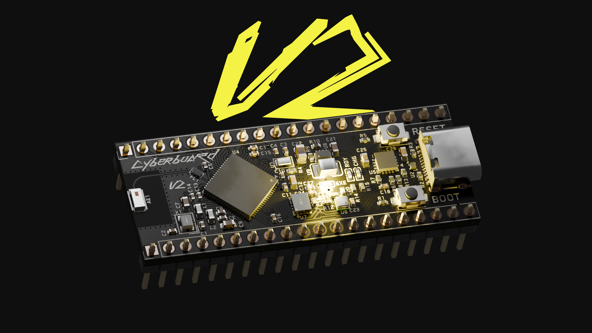
⚠️ Looking for V1? The first version of the Cyberboard is available in the v1 branch, but be warned: it doesn't work. V2 is a complete redesign with proper functionality.
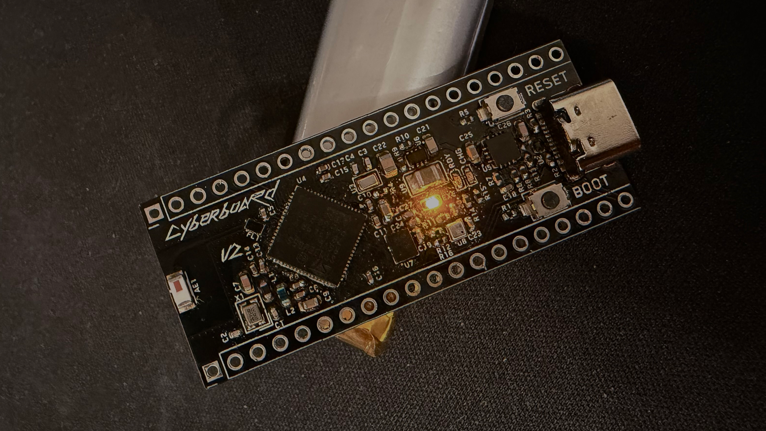
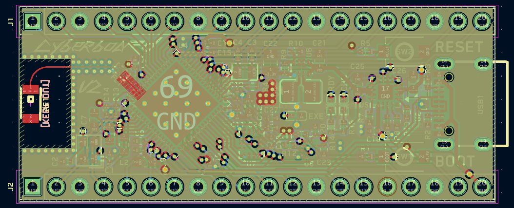
Designed in KiCad with attention to RF design, power management, and sensor integration. The board features a 4-layer stackup (SIG/GND/PWR/SIG) with optimized routing for the Bluetooth antenna and sensitive analog signals.
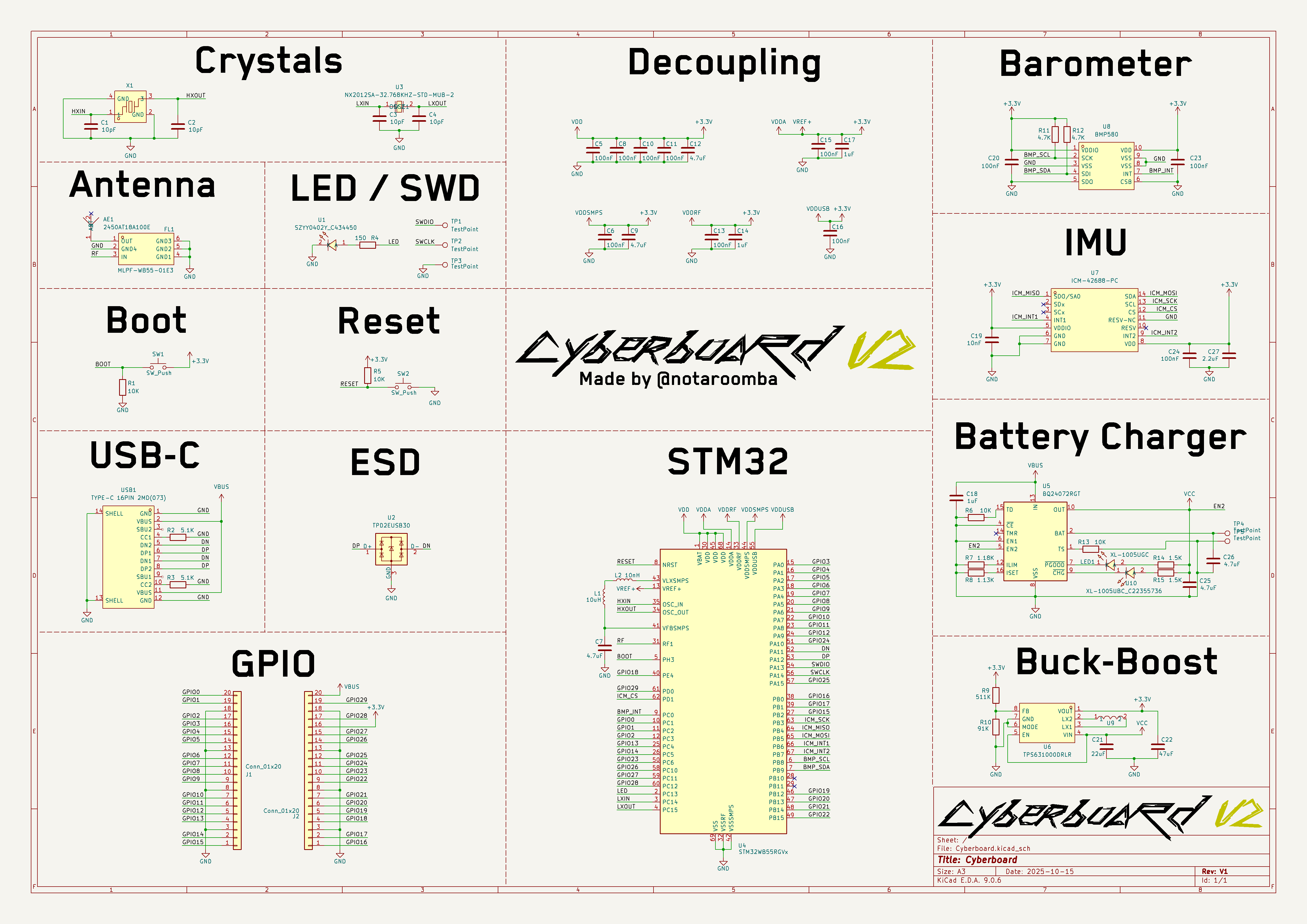
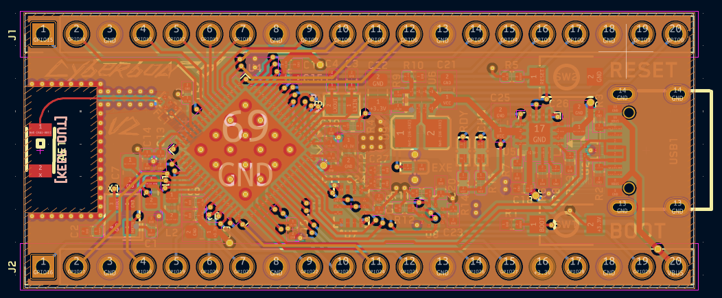
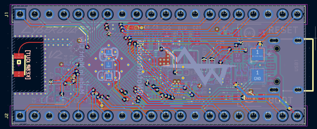
The 4-layer stackup (SIG/GND/PWR/SIG) provides optimal signal integrity and power distribution:
Layer 1 (Signal):
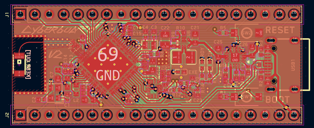
Layer 2 (Ground):
Layer 3 (Power):
Layer 4 (Signal):
Front:
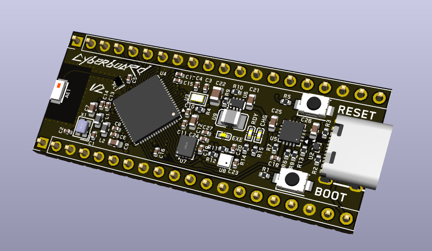
Back:
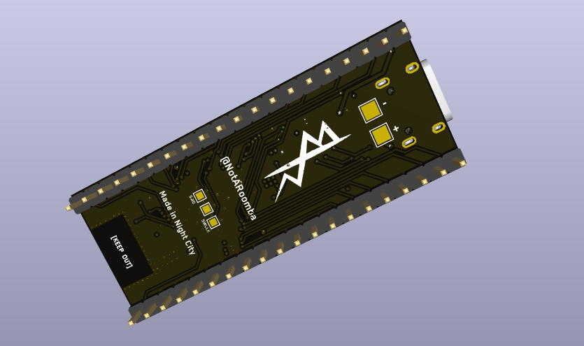
This project uses:
MIT
notaroomba.dev · GitHub @NotARoomba ·
| Qty | Value | Footprint | References |
|---|---|---|---|
| 22 | 100nF | Capacitor_SMD:C_0402_1005Metric | C10, C10, C11, C11, C13, C13, C15, C15, C16, C16, C20, C20, C23, C23, C24, C24 +6 |
| 10 | 4.7uF | Capacitor_SMD:C_0603_1608Metric | C7, C7, C9, C9, C12, C12, C25, C25, C26, C26 |
| 8 | 10K | Resistor_SMD:R_0402_1005Metric | R1, R1, R5, R5, R6, R6, R13, R13 |
| 8 | 10pF | Capacitor_SMD:C_0402_1005Metric | C1, C1, C2, C2, C3, C3, C4, C4 |
| 6 | 1uF | Capacitor_SMD:C_0402_1005Metric | C14, C14, C17, C17, C18, C18 |
| 6 | 4.7K | Resistor_SMD:R_0402_1005Metric | R11, R11, R12, R12, R16, R16 |
| 6 | TestPoint | TestPoint:TestPoint_Pad_1.0x1.0mm | TP1, TP1, TP2, TP2, TP3, TP3 |
| 4 | 1.5K | Resistor_SMD:R_0402_1005Metric | R14, R14, R15, R15 |
| 4 | 5.1K | Resistor_SMD:R_0402_1005Metric | R2, R2, R3, R3 |
| 4 | Conn_01x20 | Connector_PinHeader_2.54mm:PinHeader_1x20_P2.54mm_Vertical | J1, J1, J2, J2 |
| 4 | SW_Push | lcsc:SW-SMD_L3.9-W3.0-P4.45 | SW1, SW1, SW2, SW2 |
| 4 | TestPoint | TestPoint:TestPoint_Pad_2.0x2.0mm | TP4, TP4, TP5, TP5 |
| 2 | 1.13K | Resistor_SMD:R_0402_1005Metric | R8, R8 |
| 2 | 1.18K | Resistor_SMD:R_0402_1005Metric | R7, R7 |
| 2 | 10nF | Capacitor_SMD:C_0402_1005Metric | C19, C19 |
| 2 | 10nH | Inductor_SMD:L_0603_1608Metric | L2, L2 |
| 2 | 10uH | Inductor_SMD:L_0603_1608Metric | L1, L1 |
| 2 | 150 | Resistor_SMD:R_0402_1005Metric | R4, R4 |
| 2 | 2.2uF | Capacitor_SMD:C_0402_1005Metric | C27, C27 |
| 2 | 22uF | Capacitor_SMD:C_0603_1608Metric | C21, C21 |
| 2 | 2450AT18A100E | lcsc:ANT-SMD_L3.2-W1.6 | AE1, AE1 |
| 2 | 47uF | Capacitor_SMD:C_0805_2012Metric | C22, C22 |
| 2 | 511K | Resistor_SMD:R_0402_1005Metric | R9, R9 |
| 2 | 91K | Resistor_SMD:R_0402_1005Metric | R10, R10 |
| 2 | BMP580 | lcsc:LGA-10_L2.0-W2.0-P0.50-TL_BMP580 | U8, U8 |
| 2 | BQ24072RGT | Package_DFN_QFN:VQFN-16-1EP_3x3mm_P0.5mm_EP1.6x1.6mm | U5, U5 |
| 2 | DFE252012P-1R0M=P2 | lcsc:L1008 | U9, U9 |
| 2 | ICM-42688-PC | lcsc:LGA-14_L3.0-W2.5-P0.50-TL | U7, U7 |
| 2 | MLPF-WB55-01E3 | lcsc:FILTER-SMD_6P-L1.6-W1.0-P0.50-BL | FL1, FL1 |
| 2 | NX2012SA-32.768KHZ-STD-MUB-2 | lcsc:CRYSTAL-SMD_L2.0-W1.2 | U3, U3 |
| 2 | NX2016SA-32MHZ-STD-CZS-5 | lcsc:OSC-SMD_4P-L2.0-W1.6-BL | X1, X1 |
| 2 | STM32WB55RGVx | Package_DFN_QFN:QFN-68-1EP_8x8mm_P0.4mm_EP6.4x6.4mm | U4, U4 |
| 2 | SZYY0402Y_C434450 | lcsc:LED0402-FD_YELLOW | U1, U1 |
| 2 | TPD2EUSB30 | Package_TO_SOT_SMD:Texas_DRT-3 | U2, U2 |
| 2 | TPS631000DRLR | lcsc:SOT-583-8_L2.1-W1.2-P0.50-LS1.6-BL | U6, U6 |
| 2 | TYPE-C 16PIN 2MD(073) | lcsc:USB-C-SMD_TYPE-C-6PIN-2MD-073 | USB1, USB1 |
| 2 | XL-1005UBC_C22355736 | lcsc:LED0402-RD | U10, U10 |
| 2 | XL-1005UGC | lcsc:LED0402-RD_GREEN | LED1, LED1 |


OpenDrone-hw/OpenAIO
Open-source AIO for 2-6S toothpick quads: flight controller, 4-in-1 AM32 ESC and ExpressLRS receiver, 25.5x25.5 mm.

tetraethylmethane/NIDAR-RescueSwarm
Three autonomous drones that search a flood zone, find survivors, geotag them, and drop medical kits — with no network, no pilot, and one operator who only presses start.

OdaiJ/stm32-bt-board
My attempt at following the Phil's Lab KiCad V7 tutorial on YouTube


vexpaer/vexpaers_heart
Open-source Holter ECG recorder hardware: ADS1294R, STM32WB55, microSD, BLE and USB-Pogo dock


It measures 51 × 44 mm and has 4 copper layers, 1.58 mm thick.
138 parts, built around the MLPF-WB55-01E3, BMP580, BQ24072RGTR and DFE252012P-1R0M=P2. The full list of its parts is on this page, with links to each part's symbol and footprint where PCBKit's library has them.
From the notaroomba/cyberboard repository on GitHub, at the commit this page was made from: the board is hardware/panel/Cyberboard_Panel.kicad_pcb and its schematic hardware/Cyberboard.kicad_sch. PCBKit opens the board in the browser, with nothing to install.
Its repository states no licence, so its author keeps all rights: ask notaroomba before reusing the design.