
2 layers35.9 × 47 mm
DIY Mic
TrojanPinata/DIY-Mic
A DIY microphone built using the design of DIY Perks and modified by me
23 parts36

 not-sample-text/hi-fi-mic
A custom PCB for the high-fidelity microphone project by DIY Perks, redesigned from the original stripboard version for a cleaner and more reliable build.
Mic base is an open-source printed circuit board by not-sample-text, from the not-sample-text/hi-fi-mic repository on GitHub. It is a 2-layer board of 40 × 40 mm with 25 parts on 15 nets, routed with 79 tracks and 5 vias.
It is built around the NMA0515SC. Its parts include 8 resistors, 7 capacitors, 4 connectors and 2 ICs.
A custom PCB for the high-fidelity microphone project by DIY Perks, redesigned from the original stripboard version for a cleaner and more reliable build.
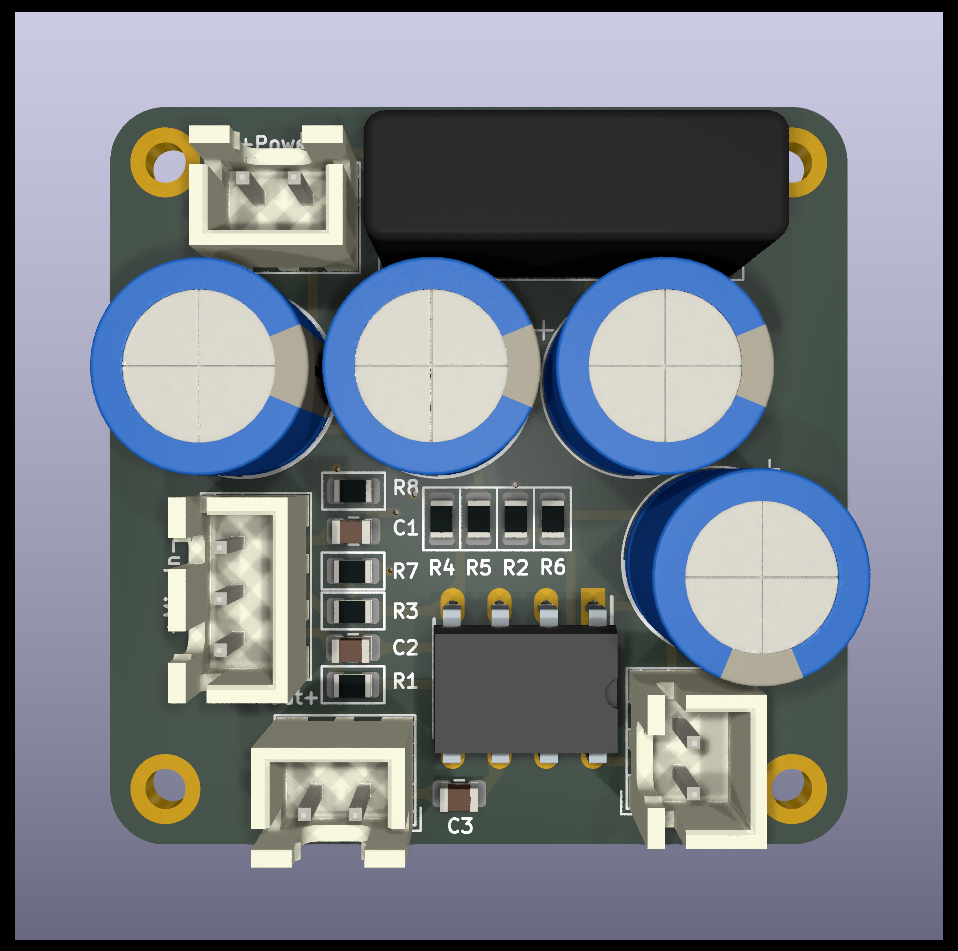
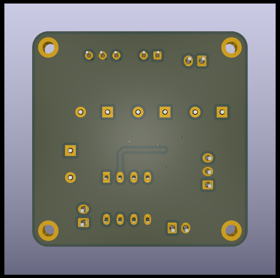
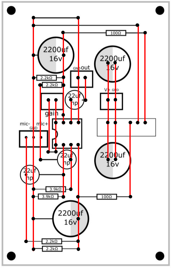
This project provides a dedicated PCB for the Hi-Fi microphone circuit originally demonstrated by DIY Perks. While the original build used a stripboard, this KiCad project offers a custom-designed PCB, making the assembly process more straightforward and the final product more durable and professional.
The project was designed in KiCad and consists of a single two-layer board.
| Front View | Back View | Initial Design |
|---|---|---|
| |  |
hi-fi-mic/
├── Imports/                  # Custom 3D models, footprints, and symbols
├── Other Files/              # Documentation (PDFs) and images
├── mic_base.kicad_pcb        # KiCad PCB layout file
├── mic_base.kicad_pro        # Main KiCad project file
├── mic_base.kicad_sch        # KiCad schematic file
└── README.md # This filemic_base.kicad_pro file to access the schematic and PCB layout.| Qty | Value | Footprint | References |
|---|---|---|---|
| 4 | 2.2k | PCM_Resistor_SMD_AKL:R_0805_2012Metric | R1, R2, R3, R4 |
| 4 | 2200uF | Capacitor_THT:CP_Radial_D10.0mm_P5.00mm | C4, C5, C6, C7 |
| 4 | MountingHole_Pad | MountingHole:MountingHole_2.2mm_M2_DIN965_Pad | H1, H2, H3, H4 |
| 3 | 22uF | Capacitor_SMD:C_0805_2012Metric | C1, C2, C3 |
| 2 | 100 | PCM_Resistor_SMD_AKL:R_0805_2012Metric | R5, R6 |
| 2 | 3.9k | PCM_Resistor_SMD_AKL:R_0805_2012Metric | R7, R8 |
| 1 | +Gain- | Connector_JST:JST_XH_B2B-XH-A_1x02_P2.50mm_Vertical | J3 |
| 1 | +Mic In- | Connector_JST:JST_XH_B3B-XH-A_1x03_P2.50mm_Vertical | J4 |
| 1 | +Power- | Connector_JST:JST_XH_B2B-XH-A_1x02_P2.50mm_Vertical | J1 |
| 1 | -Out+ | Connector_JST:JST_XH_B2B-XH-A_1x02_P2.50mm_Vertical | J2 |
| 1 | 1512P08-U | Footprints:DIP781W46P254L952H432Q8N | IC1 |
| 1 | NMA0515SC | Converter_DCDC:Converter_DCDC_Murata_NMAxxxxSC_THT | U1 |
It measures 40 × 40 mm and has 2 copper layers, 1.6 mm thick.
25 parts, built around the NMA0515SC. The full list of its parts is on this page, with links to each part's symbol and footprint where PCBKit's library has them.
From the not-sample-text/hi-fi-mic repository on GitHub, at the commit this page was made from: the board is mic_base/mic_base.kicad_pcb and its schematic mic_base/mic_base.kicad_sch. PCBKit opens the board in the browser, with nothing to install.
Its repository states no licence, so its author keeps all rights: ask not-sample-text before reusing the design.
TrojanPinata/DIY-Mic
A DIY microphone built using the design of DIY Perks and modified by me

atomlaser-lab/iq-bias-control
Digital bias controller for IQ single-sideband modulation using a Red Pitaya STEMlab board

lmarzen/diy-microphone
This project contributes a KiCad PCB design that implements the circuit described in the DIY Perks Microphone Project v1, https://www.youtube.com/watch?v=LoQu3XXIayc.

Gadu1in/audio-interface-pcm2906
An audio interface designed for low impedance earbuds and an external 3.5mm microphone input


google/mozc-devices
Circuit diagrams and firmware source code for Gboard DIY keyboards

davidphilipbarr/Sweep
Sweep - a small promicro based keyboard inspired by the Ferris.