2 layers99.5 × 83.1 mm
 NoseFa/splitkb2
A wireless split low-profile keyboard with a nordic layout
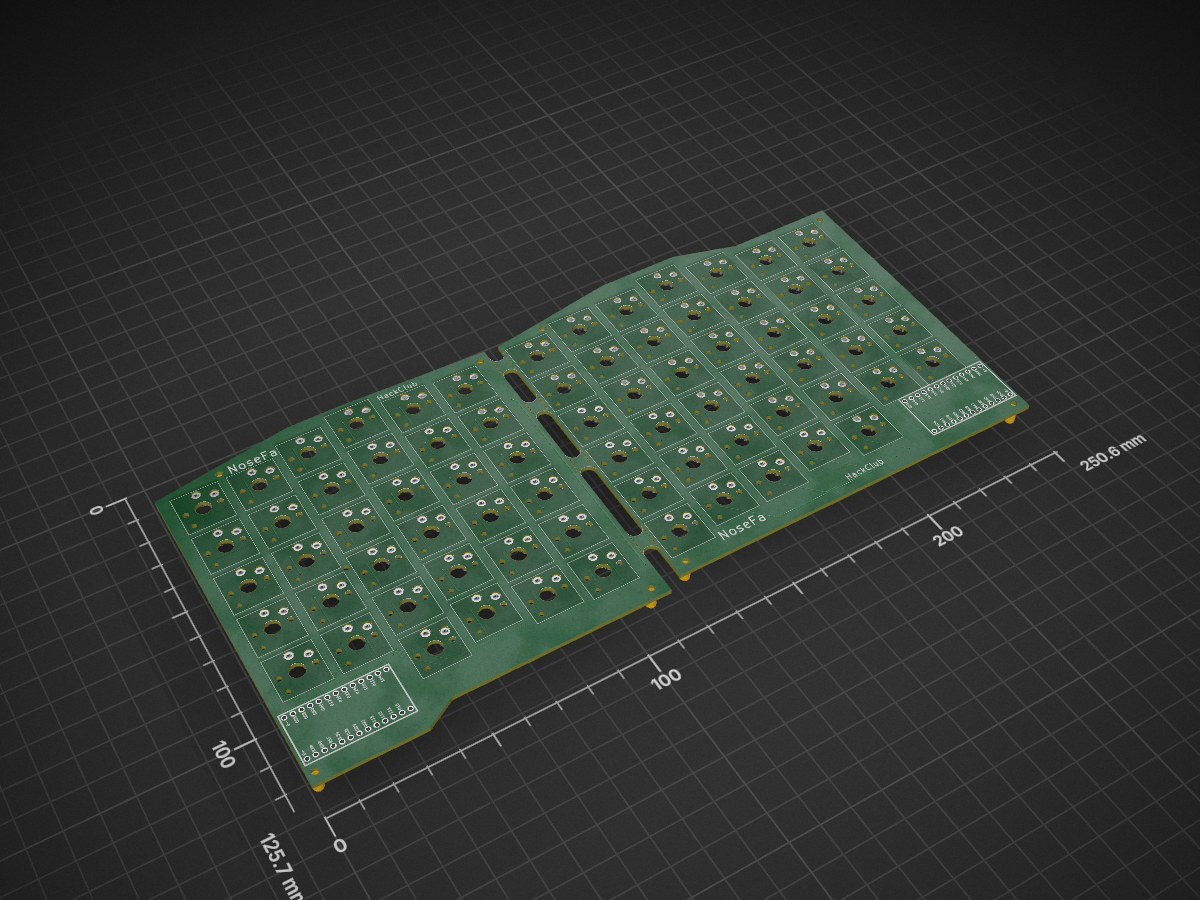
Splitkb is an open-source printed circuit board by NoseFa, from the NoseFa/splitkb repository on GitHub, published under the MIT licence. It is a 2-layer board of 250.6 × 125.7 mm with 166 parts on 126 nets, routed with 940 tracks and 138 vias.
Its parts include 74 diodes, 74 switches and 2 ICs. It belongs with the keyboards and input boards and the nRF52 and nRF5x boards of this library.
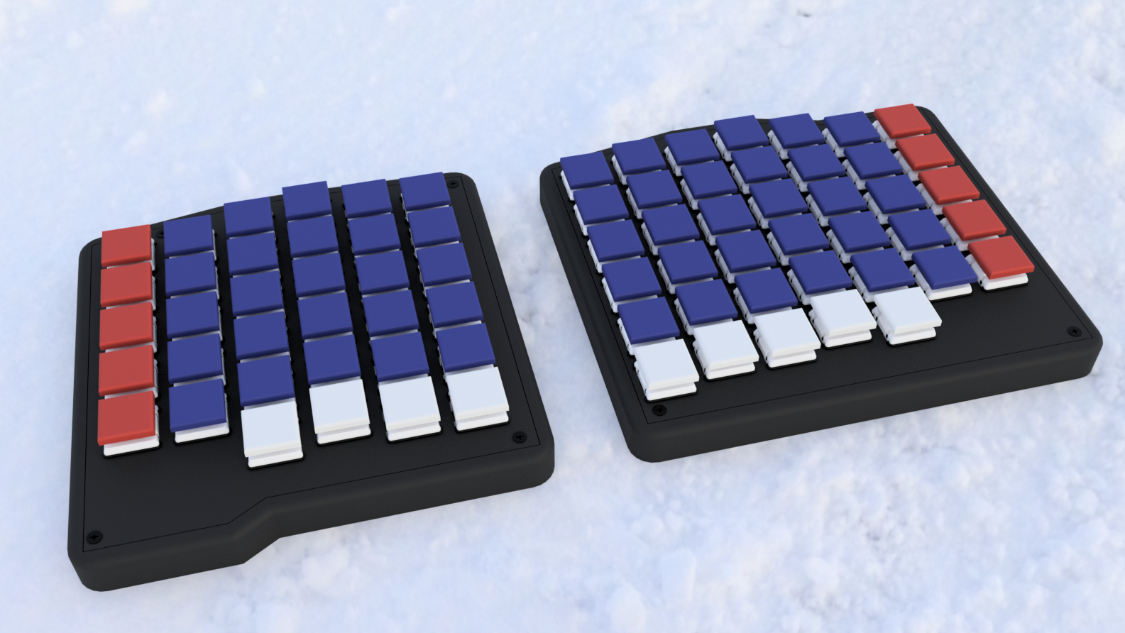
A split low-profile wireless keyboard with a nordic ISO layout. I used the Caldera Keyboard by Christian Selig as inspiration and it clearly shows in the design. Still the keyboard uses a nice!nano like microcontroller based on the same NRF52840, ZMK as the firmware and a custom pcb with Choc V1 hotswap sockets. The keyboard also has an ortholinear layout which can be more ergonomic for some users.
The project was made and designed as a part of Hack Club's Fallout event where people make hardware projects and get a chance to go to Shenzhen, China. This was also one of my first electronics projects.
The project was made because I wanted a split keyboard but needed a nordic layout for my day to day stuff (I need the letters Ä, Ö, Å). So the nordic split was born. I took inspiration from the Caldera keyboard by Christian Selig. It's low profile so it can be transported easily around and it's also wireless so no need for annoying dual or split cables for connecting to a computer or laptop.
This is the first keyboard I have designed so the keymap and layout were made with some educated guess work. They might be updated later down the line. I will update this repo with the most recent keymap I use. Even though it was designed as nordic layout first. The keyboard could also be used by people with non-nordic layouts and you could use the extra row of keys on the right side as shortcut or macro keys. Of course also the pcb could be edited and these keys removed if you don't want them. This keyboard has ZMK studio support so you can change the keymap in the ZMK.studio web app.
Total price for the whole build excluding 3d prints is 159.26€.
You can find the full BOM here. It includes pricing, amount of parts, extra info etc.
More detailed build guide is available in the build guide.md file.
See Software.md for more info about software and software installation instructions. The software source code files are in a different repo (NoseFa/nordic-split-zmk)
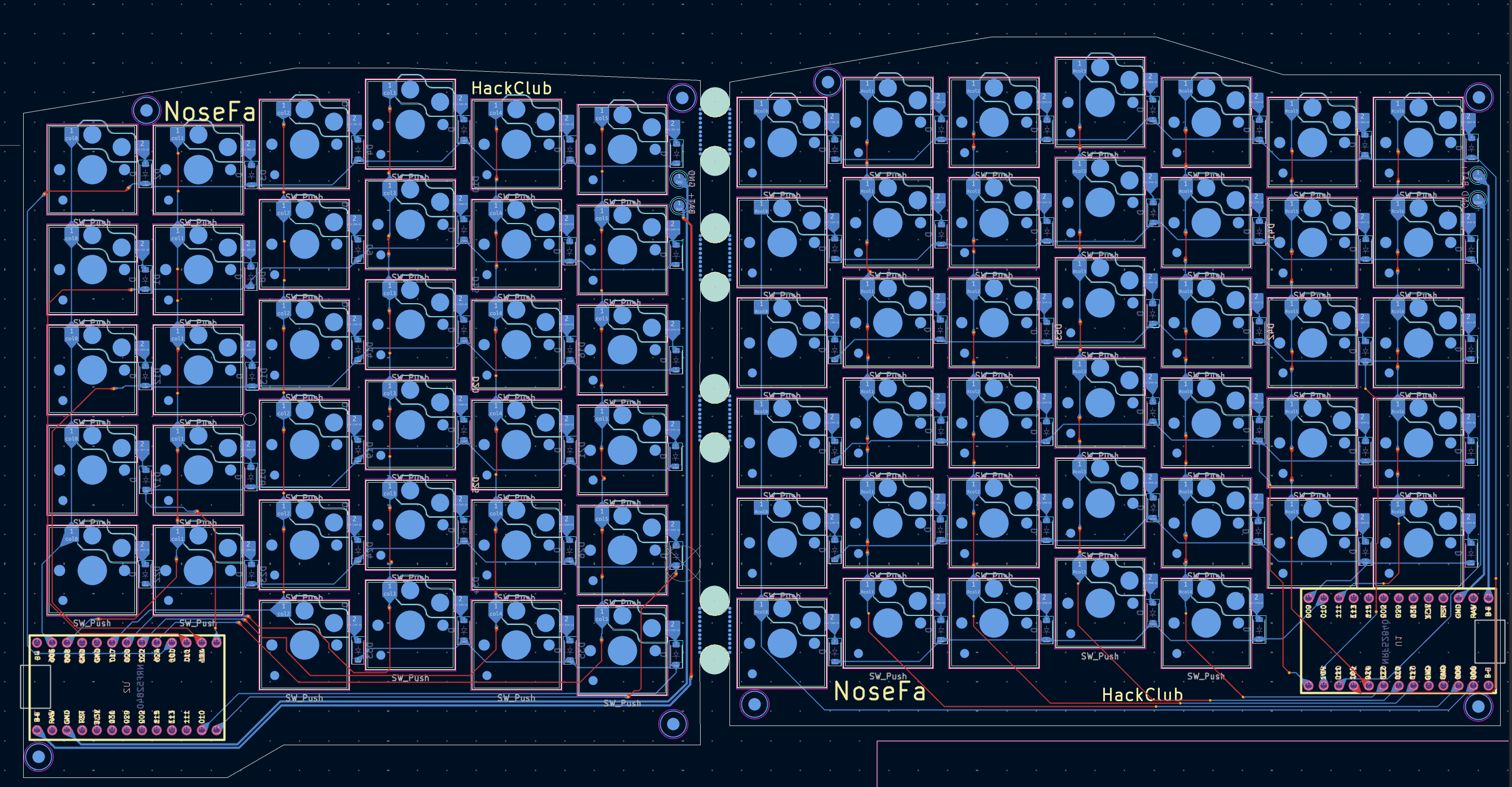
Here is a picture of the left side PCB. You can see the switches, traces and a spot for the microcontrollers. The PCBs are seperated by mouse bites in the middle. Unlike some other split keyboards the Nordic Splits halves aren't mirrored but instead the right side has an extra row of keys primarly needed to support the Nordic layout.
The pcb was designed in KiCad by me. You can view the files in the Kicad folder.
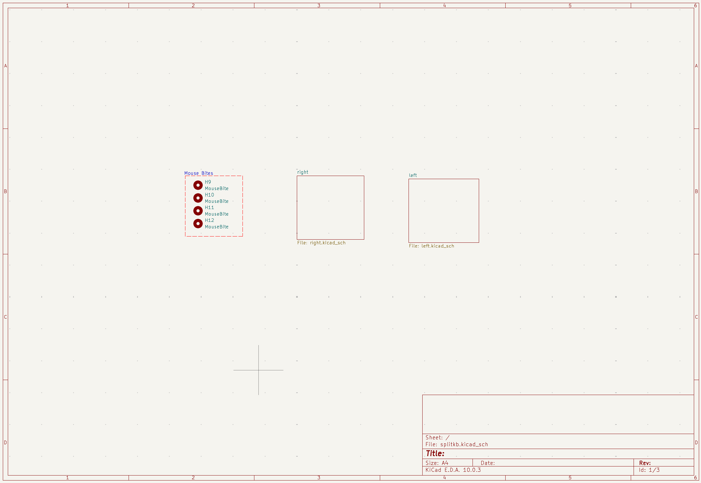
Here is also the schematic which is split into three different pages. One for each side and one main page that has the mousebites and links the pages together.
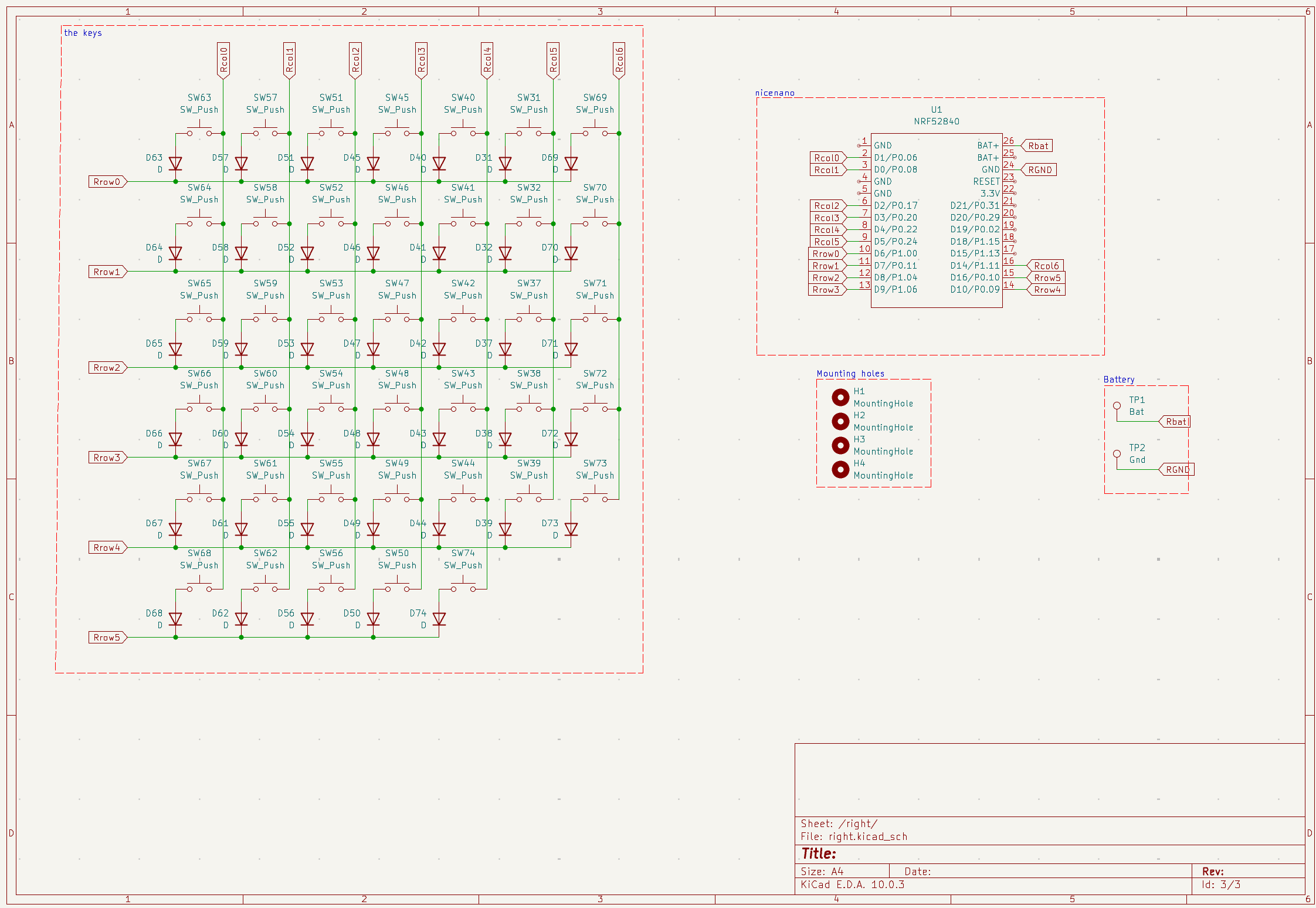
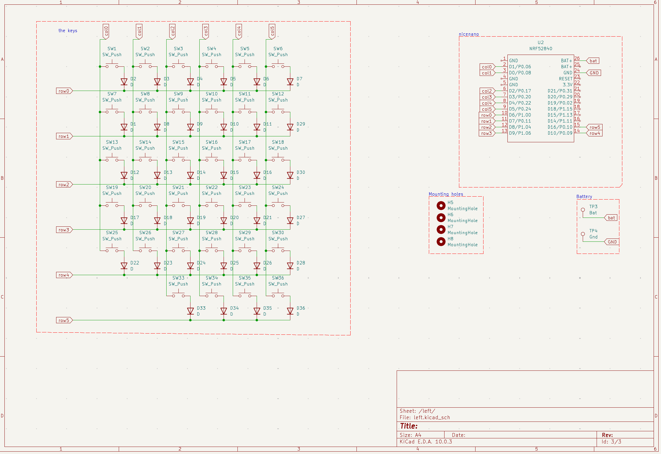
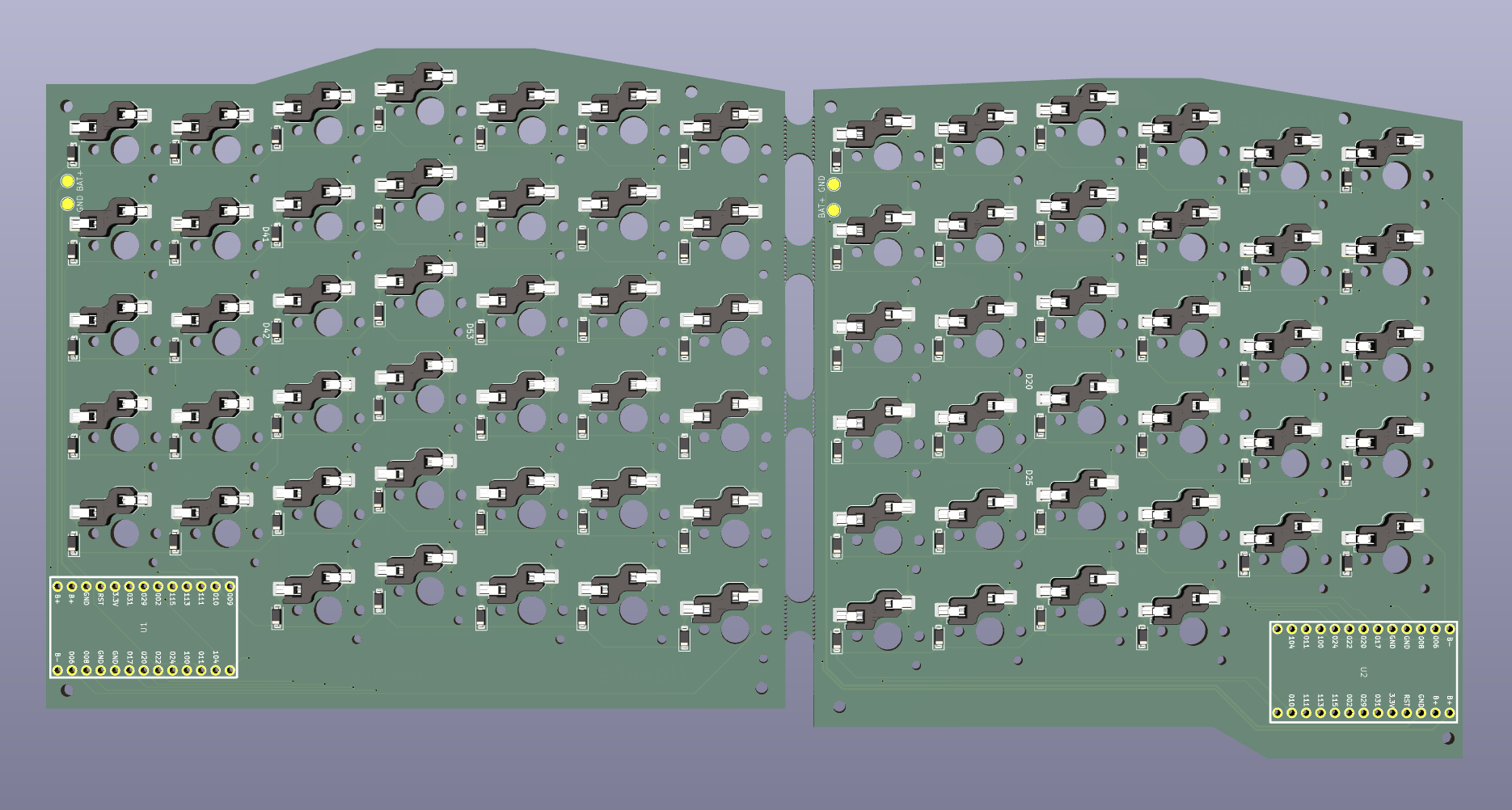
For ordering the PCB I used JLCPCB. You can find the gerber files as a zip in the Production files folder
3d Files are seperated into 2 folders. Full project which has the .fz3 and .step versions of the whole 3D project. The PCB was exported when I finished the the edge cuts so some holes next to the micro controller might be different. I didn't include the microcontroller or the SMD diodes in the 3d project but I did check that they fit.
The 3d files for the switches in the Fusion project are from printables. They are made by cobypear. They are originally from the same library as I used in kicad which is the kiswitch library. You can find the original files from the link.
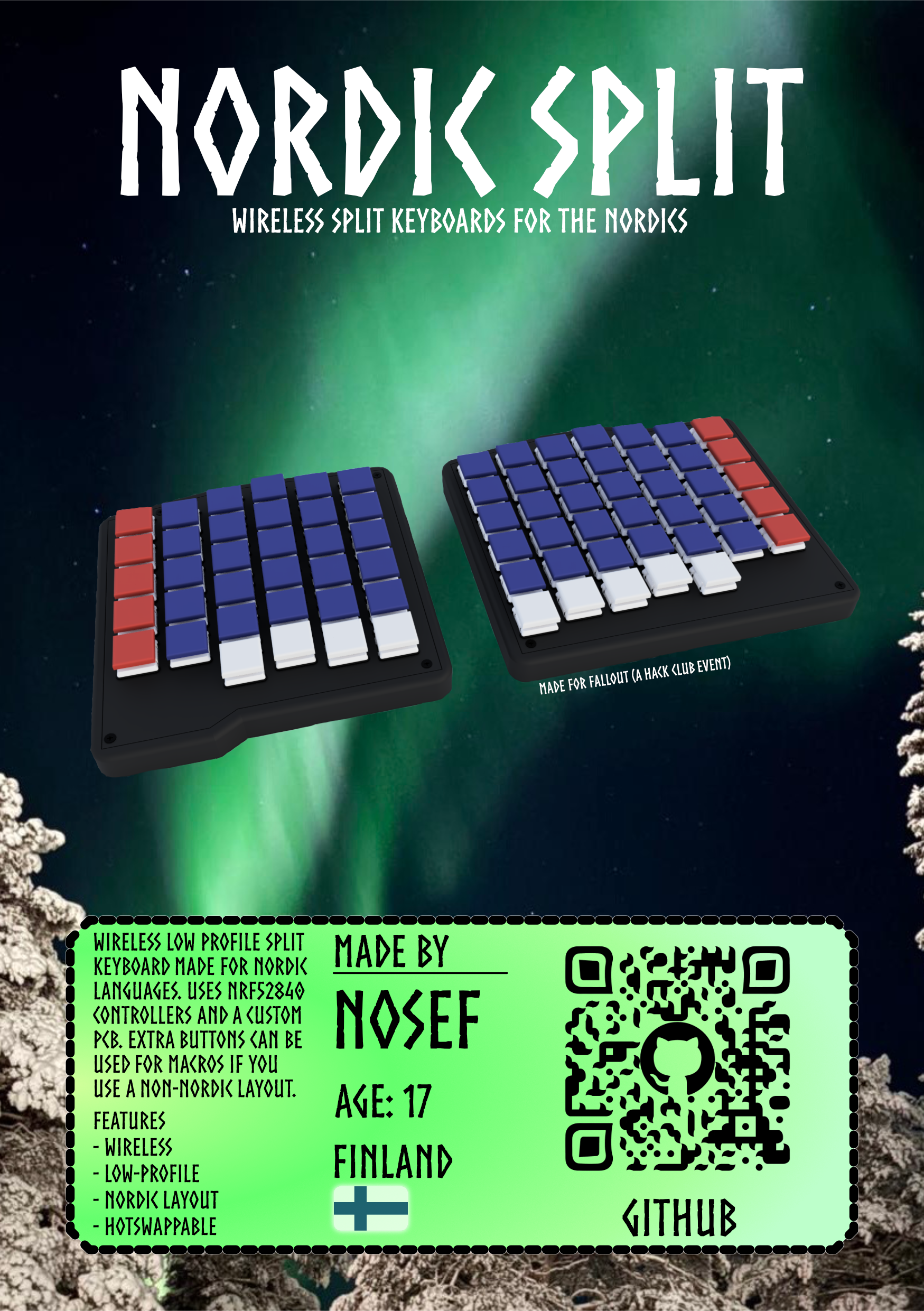
Zine page is also available as a PDF. Background picture was taken by my dad when we went up north.
A video of the keyboard in use.
SOON (When I get the parts).
Thanks to Hack Club Fallout. If you want to view the project I made for Fallout including journals you can view it on the event page.
Caldera Keyboard by Christian Selig was used as inspiration and his video was a great watch. My design is clearly inspired by him.
| Qty | Value | Footprint | References |
|---|---|---|---|
| 74 | D | Diode_SMD:D_SOD-123 | D1, D2, D10, D11, D12, D13, D14, D15, D16, D17, D18, D19, D20, D21, D22, D23 +58 |
| 74 | SW_Push | PCM_Switch_Keyboard_Hotswap_Kailh:SW_Hotswap_Kailh_Choc_V1V2 | SW1, SW2, SW10, SW11, SW12, SW13, SW14, SW15, SW16, SW17, SW18, SW19, SW20, SW21, SW22, SW23 +58 |
| 4 | MountingHole | MountingHole:MountingHole_2.2mm_M2 | H1, H2, H3, H4 |
| 4 | MouseBite | Panelization.pretty-master:mouse-bite-5mm-slot | H9, H10, H11, H12 |
| 2 | Bat | TestPoint:TestPoint_Pad_D2.0mm | TP1, TP1 |
| 2 | Gnd | TestPoint:TestPoint_Pad_D2.0mm | TP2, TP2 |
| 2 | NRF52840 | nice-nano-kicad-master:NRF52840 | U1, U2 |
The 162 most common of 166 parts.
It measures 250.6 × 125.7 mm and has 2 copper layers, 1.6 mm thick.
166 parts. The full list of its parts is on this page, with links to each part's symbol and footprint where PCBKit's library has them.
From the NoseFa/splitkb repository on GitHub, at the commit this page was made from: the board is KICAD/splitkb/splitkb.kicad_pcb and its schematic KICAD/splitkb/left.kicad_sch. PCBKit opens the board in the browser, with nothing to install.
Its repository publishes it under the MIT licence: you may reuse it on that licence's terms (keep the author's notice, and for a copyleft licence share your changes alike).


schlae/HardDriveInfo
Repair info and schematics for mostly older MFM hard drives

Thorinair/Avalon-Harmonics
A collection of Avalon Harmonics branded synthesizer modules.

doppelhub/Honda_Insight_LiBCM
Replacement BCM for G1 Honda Insight Lithium Conversion

OpenLogicEFI/Hardware
Hardware is based off an open source project called Speeduino by Josh Stewart.
