
4 layers180.8 × 300.3 mm
Dilemma
Bastardkb/Dilemma
The Dilemma is a vertical stagger low-profile keyboard with mods.
383 parts590
I made this project using the base of the hackclub starter projects of the split keyboard but also im adding a knob on each side one for sound and one for screen brightness adjustment
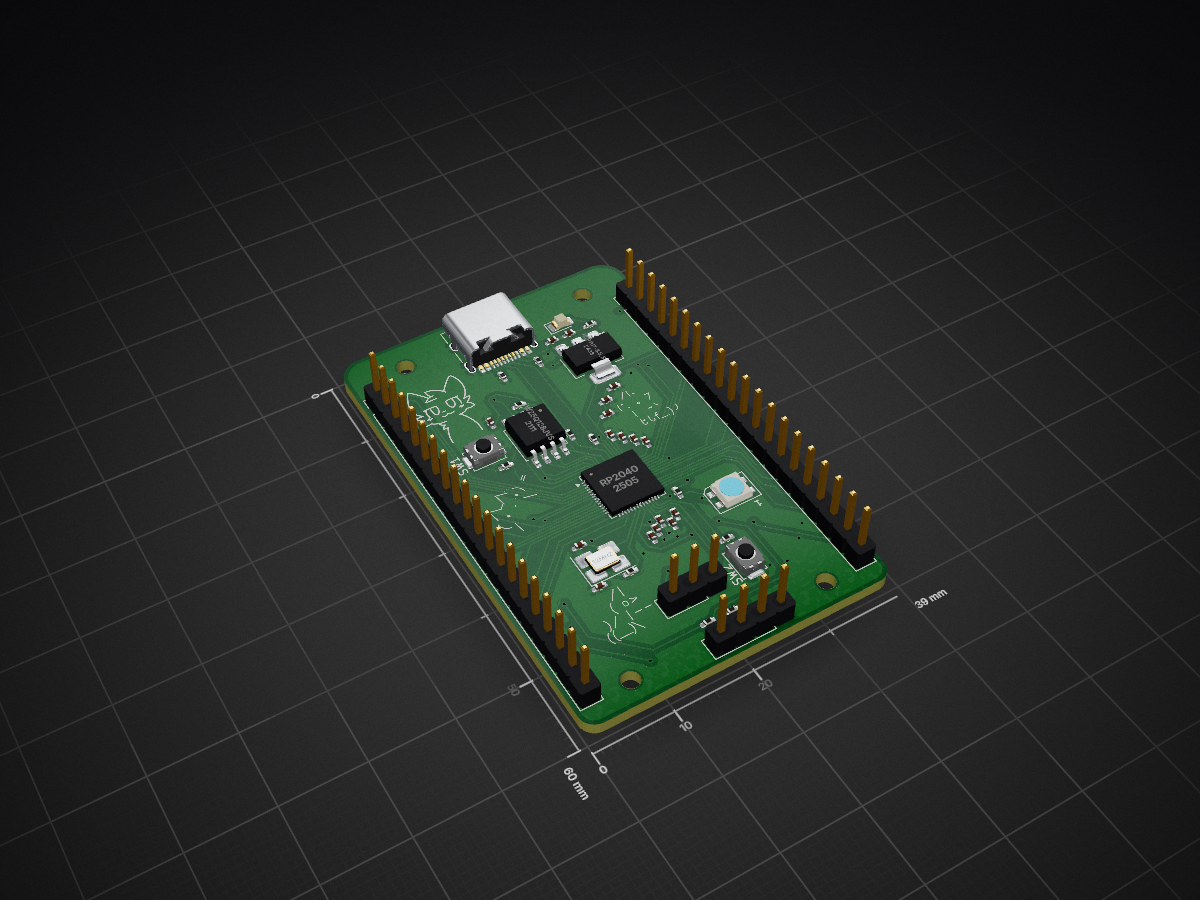
Devboard is an open-source printed circuit board by norayr-noro, from the norayr-noro/Split_keyboard-with-adjustable-knobs repository on GitHub. It is a 2-layer board of 39 × 60 mm with 46 parts on 61 nets, routed with 480 tracks and 44 vias.
It is built around the RP2040, W25Q128JVSIQ and SK6812MINI-E. Its parts include 17 capacitors, 12 resistors, 5 connectors, 3 ICs and 2 diodes. It belongs with the microcontroller boards and keyboards and input boards and the RP2040 boards of this library.


Making your own keyboard sounds difficult, but it really isn't! And this repo is proof of that. As a beginner in the field of CAD and PCB design, this is an ideal project to make because it combines areas like PCB and CAD modeling, and in this repo, I'll be writing on how I built it following the guide on hackclub stasis!
Here I'll put down all the components I will likely use in the full project:
| ITEM | URL | QUANTITY | PRICE (USD) |
|---|---|---|---|
| cherry-mx style switches | https://www.ebay.co.uk/itm/187479375359 | 56 | 14.58 |
| 1N5819 diodes | https://www.rapidonline.com/st-1n5819-schottky-diode-40v-1a-do41-47-2566 | 56 | 5.4 |
| Raspberry Pi Pico W | https://shorturl.at/rgenT | 2 | 15.57 |
| EC11E rotary encoders | https://www.adafruit.com/product/377 | 2 | 9 |
| LiPo batteries (1500mah) | https://shorturl.at/IHMxN | 2 | 18.79 |
| TP4056 modules | https://www.ebay.co.uk/itm/295410567795?var=593544577789 | 2 | 3.22 |
| SS12D10 slide switches | https://shorturl.at/kdSMI | 2 | 2.68 |
All libraries I used are in the Stasis Hackclub guide(https://stasis.hackclub.com/starter-projects/split-keyboard) + I also used the symbols and footprints for the Raspberry Pi from ScottoKeeb's (I recommend checking him out for anything custom keyboard related!!his YouTube channel is https://www.youtube.com/watch?v=8WXpGTIbxlQ&list=PLBD2IS_t_iWZDMdG_ZF57x9Ebm3kxKqxF&index=3)
Because I used the hackclbu split keyboard tutorial as a foundation, one of the biggest changes was switching from the XIAO nRF52840 (SMD) to the Raspberry Pi Pico. The reason for that is mostly for convenience, as I had a few picos lying around and also more GPIO pins to make a proper keyboard.(more pins = more rows/columbs = more keys), And with the diode+switch matrix would make an ideal build.
I also added these rotary encoders(one in each hand) to control the sound and brightness of the screen. These just make the design more fun and unique, and it would not change a lot if these were not on the PCB, so feel free to change stuff around!
Changed the full design of the PCB to make it as slim as possible (could've done better tbh) to lower the cost of manufacturing the PCB + the fact it would look like a cleaner and nicer build in general. After that, I shifted the Pico W upwards (all the wayyyyyy to the edge) for easier access to the USB port and simpler routing and debugging Continuing with those changes, I moved on to the CAD models, changed the case and plate to fit the new PCB, and mostly did some polishing for where the USB-C would go and where the slide switch should go.
I also put the pico to the edge to easily debug and a lot of dat. Cant wait to build this!
Herese the final full assembly of the case and plate (looks a bit chonky but still not bad): (THE NEW MODEL)
I'll also attach the .step file for the PCB and the .f3d file for the 3d model i have worked on to this repository for future reference...
| Qty | Value | Footprint | References |
|---|---|---|---|
| 11 | 0.1uF | Capacitor_SMD:C_0402_1005Metric_Pad0.74x0.62mm_HandSolder | C1, C2, C3, C4, C5, C6, C7, C8, C10, C11, C16 |
| 4 | 1uF | Capacitor_SMD:C_0402_1005Metric_Pad0.74x0.62mm_HandSolder | C0, C9, C12, C13 |
| 4 | MountingHole | MountingHole:MountingHole_2.2mm_M2 | H1, H2, H3, H4 |
| 3 | 1K | Resistor_SMD:R_0402_1005Metric_Pad0.72x0.64mm_HandSolder | R5, R7, R10 |
| 2 | 10K | Resistor_SMD:R_0402_1005Metric_Pad0.72x0.64mm_HandSolder | R6, R9 |
| 2 | 27 | Resistor_SMD:R_0402_1005Metric_Pad0.72x0.64mm_HandSolder | R3, R4 |
| 2 | 4.7K | Resistor_SMD:R_0402_1005Metric_Pad0.72x0.64mm_HandSolder | R12, R13 |
| 2 | 5.1K | Resistor_SMD:R_0402_1005Metric_Pad0.72x0.64mm_HandSolder | R1, R2 |
| 2 | 8pf | Capacitor_SMD:C_0402_1005Metric_Pad0.74x0.62mm_HandSolder | C14, C15 |
| 2 | Conn_01x20 | Connector_PinHeader_2.54mm:PinHeader_1x20_P2.54mm_Vertical | J4, J5 |
| 2 | SW_Push | Button_Switch_SMD:SW_Push_SPST_NO_Alps_SKRK | SW1, SW2 |
| 1 | 12MHz | Crystal:Crystal_SMD_3225-4Pin_3.2x2.5mm_HandSoldering | Y1 |
| 1 | 330 | Resistor_SMD:R_0402_1005Metric_Pad0.72x0.64mm_HandSolder | R8 |
| 1 | Conn_01x03 | Connector_PinHeader_2.54mm:PinHeader_1x03_P2.54mm_Vertical | J6 |
| 1 | I2C | Connector_PinHeader_2.54mm:PinHeader_1x04_P2.54mm_Vertical | J2 |
| 1 | LED | LED_SMD:LED_0805_2012Metric_Pad1.15x1.40mm_HandSolder | D2 |
| 1 | NCP1117-3.3_SOT223 | Package_TO_SOT_SMD:SOT-223-3_TabPin2 | U2 |
| 1 | RP2040 | Package_DFN_QFN:QFN-56-1EP_7x7mm_P0.4mm_EP3.2x3.2mm | U1 |
| 1 | SK6812MINI | LED_SMD:LED_SK6812MINI_PLCC4_3.5x3.5mm_P1.75mm | D1 |
| 1 | USB_C_Receptacle_USB2.0_14P | Connector_USB:USB_C_Receptacle_HRO_TYPE-C-31-M-12 | J1 |
| 1 | W25Q128JVS | Package_SO:SOIC-8_5.3x5.3mm_P1.27mm | U3 |
It measures 39 × 60 mm and has 2 copper layers, 1.6 mm thick.
46 parts, built around the RP2040, W25Q128JVSIQ and SK6812MINI-E. The full list of its parts is on this page, with links to each part's symbol and footprint where PCBKit's library has them.
From the norayr-noro/Split_keyboard-with-adjustable-knobs repository on GitHub, at the commit this page was made from: the board is PCB_meowboard/Devboard.kicad_pcb and its schematic PCB_meowboard/Devboard.kicad_sch. PCBKit opens the board in the browser, with nothing to install.
Its repository states no licence, so its author keeps all rights: ask norayr-noro before reusing the design.
Bastardkb/Dilemma
The Dilemma is a vertical stagger low-profile keyboard with mods.

weteor/Qazikat
qaz-like keyboard with offset space, arrow cluster and ISO-enter


yuz207/agentpad13
agentpad13 — open-source 13-key macropad for agentic work (RP2040, vial-qmk, planar joystick, Raw HID agent-status protocol)

defvs/minigeki
A portable implementation of an ONGEKI controller, with all necessary buttons, two macros, RGB LED support, USB-C.

slopus/codex-keybored
A 100% vibe-coded hardware build: Fusion 360, six-layer KiCad PCB, STM32 firmware, and live JLC factory handoff.


BigTuna94/RP2.65-F
RP2.65-F Mechanical Keyboard - a 65% Ortholinear Keyboard with Faders