Macropad pcb is an open-source printed circuit board by nolanwon, from the nolanwon/macropad repository on GitHub, published under the MIT licence. It is a 2-layer board of 101 × 151.3 mm with 71 parts on 73 nets, routed with 810 tracks and 172 vias.
It is built around the 1N4148W and SK6812MINI-E. Its parts include 40 diodes, 3 switches, 2 ICs, 1 capacitor and 1 resistor. It belongs with the keyboards and input and lEDs and displays boards and the RP2040 boards of this library.
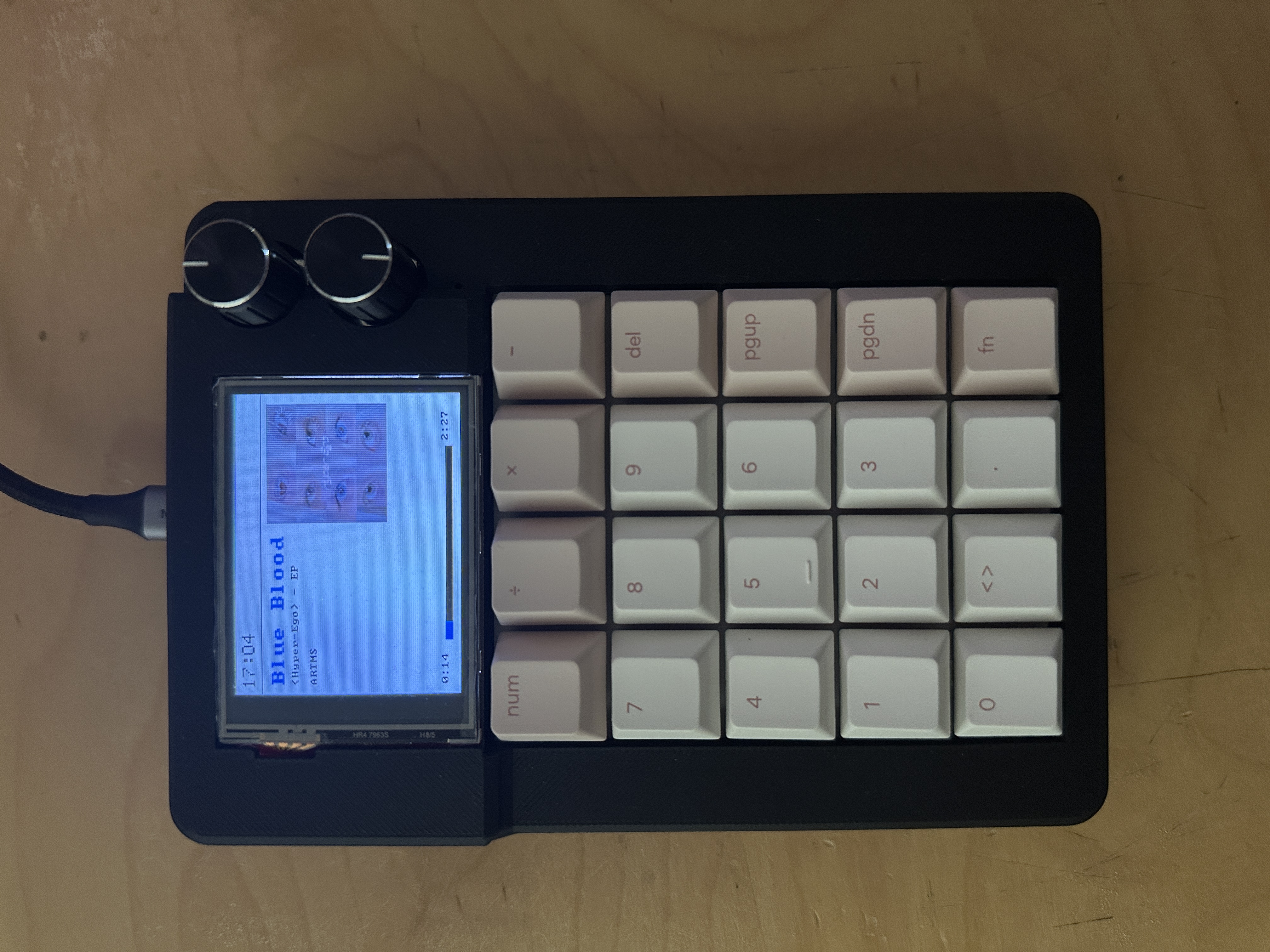
A fully custom, numpad-sized mechanical macropad with a custom PCB, hand-soldered assembly, 3D-printed enclosure, and firmware written from scratch. Features a color TFT display with a full menu system, per-key RGB backlighting, dual rotary encoders, and a built-in dual-core game mode.
Gallery
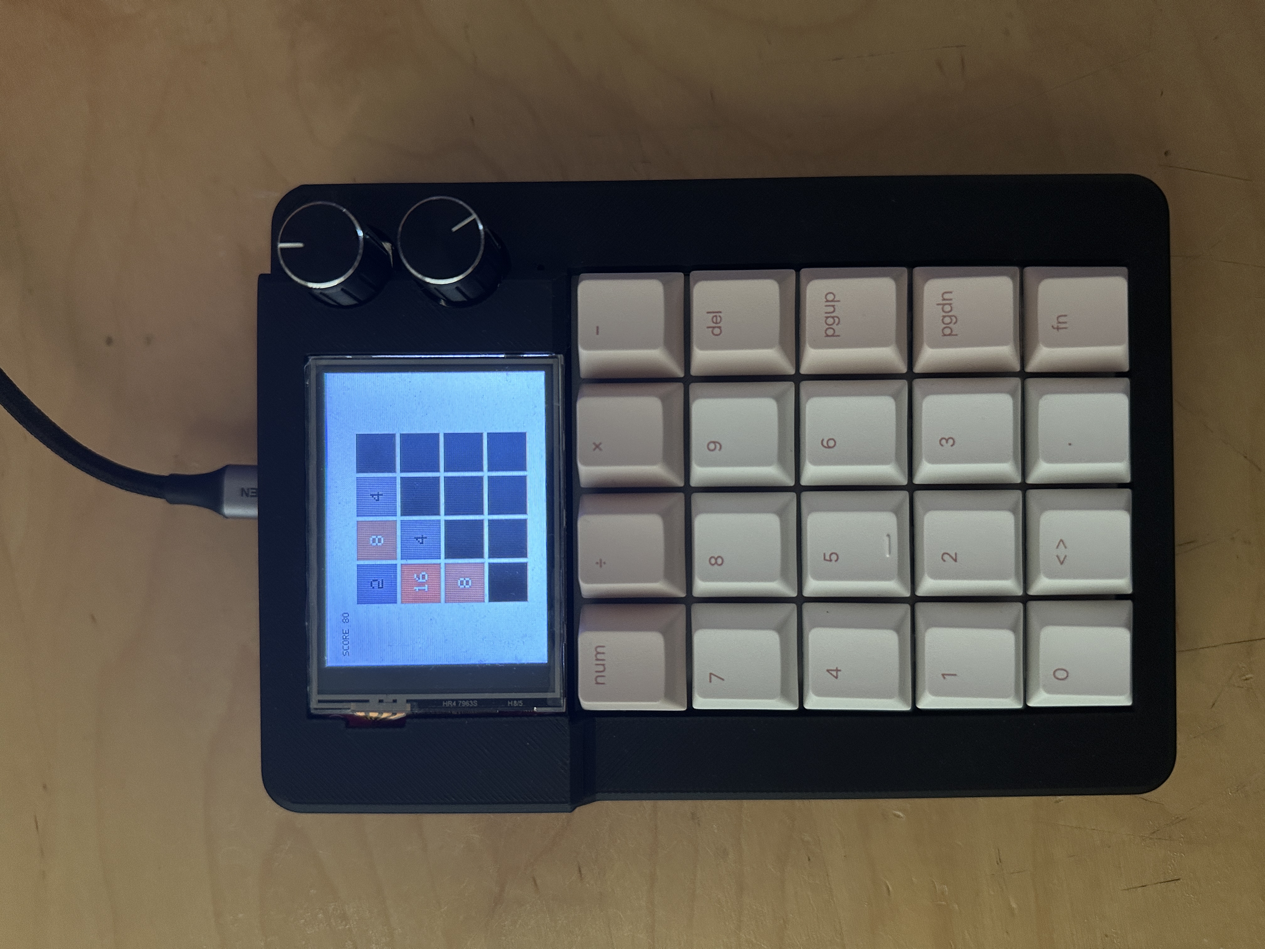
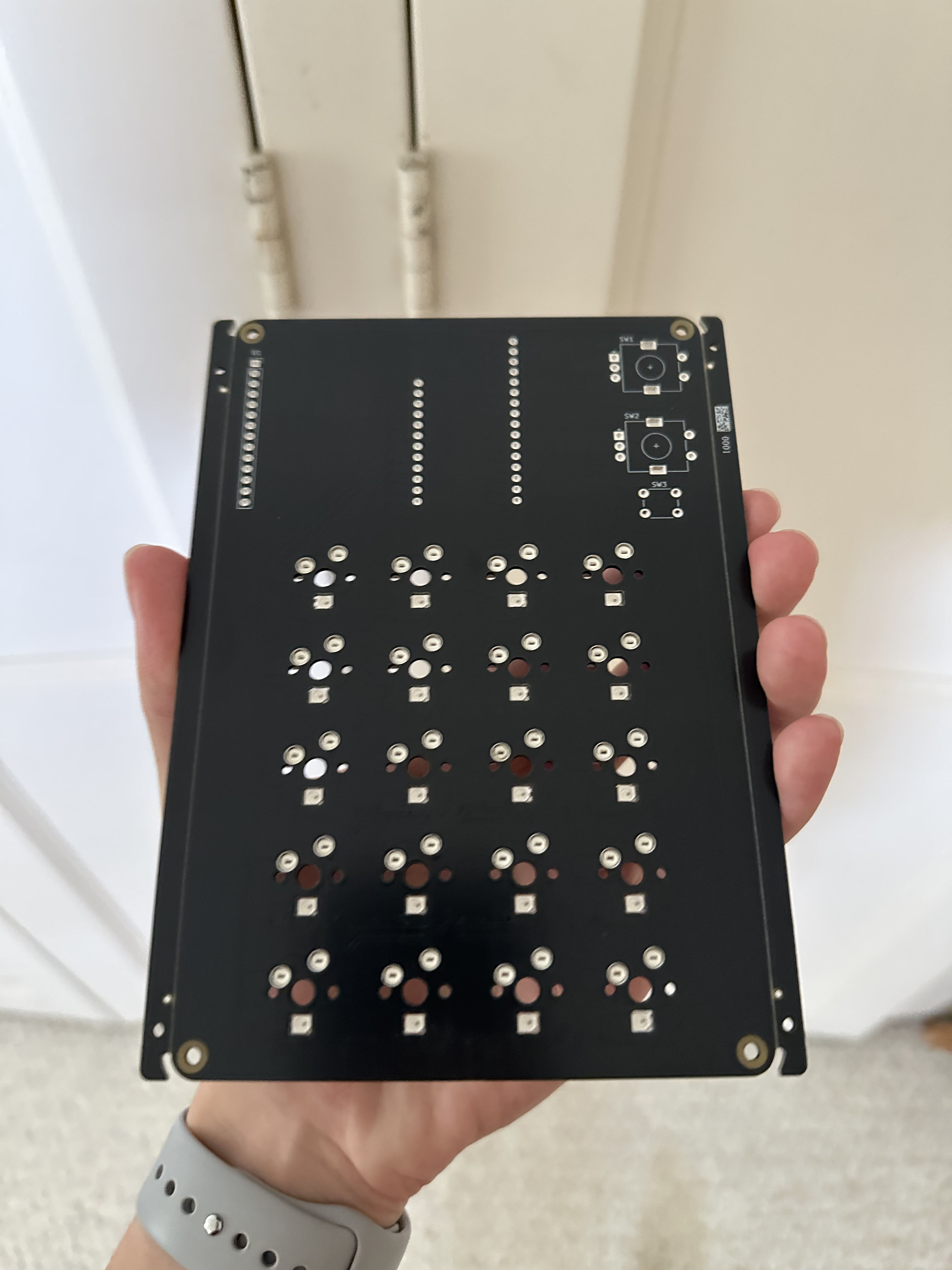
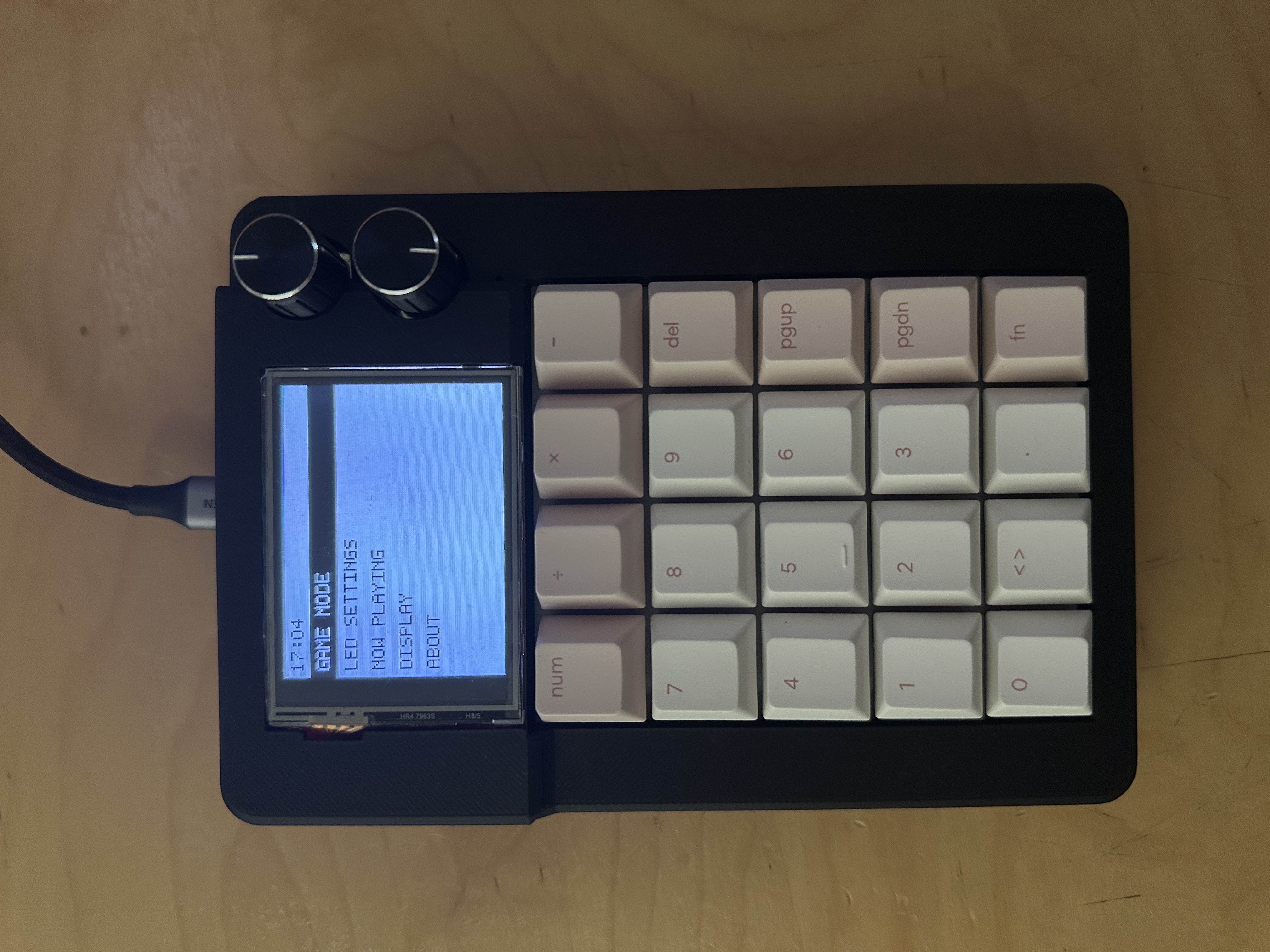
Images (top to bottom, L to R): Assembled macropad showing now playing view, 2048 game, Bare PCB, Display showing main menu
Overview
This is a 5×4 (20-key) macropad built end-to-end: schematic and PCB layout in KiCad, fabrication and partial assembly through JLCPCB, a 3D-printed SolidWorks enclosure, and custom C firmware on an RP2040 running on the Pico SDK and TinyUSB (no QMK), no third-party keyboard firmware.
Highlights
20-key hotswappable mechanical switch matrix with per-key RGB
2.4" 320×240 SPI TFT display with a full menu system and theming
Two rotary encoders for volume control and menu navigation
Two playable games (2048 and dual-core Snake) built directly into the firmware
Composite USB HID device (keyboard + consumer control)
Custom-designed PCB and enclosure, fully hand-assembled
Hardware
Component
Details
MCU
Adafruit Feather RP2040, socketed via machine-pin strips (removable, no direct soldering)
Enumerates as a composite HID device with two report IDs: a standard keyboard report and a consumer-control report (used for volume via the top encoder). No USB serial/stdio, the display serves as the primary feedback and debug surface.
Display & UI
Custom screen-manager state machine: each screen exposes init / draw / on_encoder / on_click / on_leave function pointers, switched via screen_switch_to() and unwound with a context-aware screen_manager_go_back().
iPod-style scrollable main menu leading to About, LED Settings, Display Settings, Now Playing, and Game Mode.
Fully hand-authored 5×7 bitmap font (digits, punctuation, and full upper/lowercase alphabet) with no external font library, for licensing cleanliness.
Theme system with multiple presets (including a Catppuccin Mocha theme) and a global invert flag; every screen pulls its colors from the active theme.
Status bar shows device uptime and is suppressed during full-screen game modes.
Per-key RGB
Driven over a single GPIO via PIO, with a decoupled led_config layer (power, brightness, hue/saturation/lightness, live HSL→RGB preview) exposed through the LED Settings screen.
Game Mode
A dedicated key combination suspends normal HID output and hands key events to the active game instead:
2048: turn-based, single-core, mapped to the physical numpad directional legends.
Snake: real-time, dual-core: Core 1 owns the display exclusively during gameplay and does incremental cell-level rendering, while Core 0 forwards input over multicore_fifo. A blocking start/stop handshake between the cores guarantees clean handoff of the SPI bus with no display corruption on exit.
The game-select screen is a scrollable list, built to accept additional games beyond the two included.
Building the Firmware
Prerequisites
VS Code with the Raspberry Pi Pico extension (installs the SDK, ARM GCC toolchain, CMake, and Ninja)
Pico SDK with the TinyUSB submodule initialized (lib/tinyusb)
Steps
bash
git clone https://github.com/nolanwon/macropad.git
cd macropad
# open in VS Code with the Raspberry Pi Pico extension, or:
mkdir build && cd build
cmake -DPICO_BOARD=adafruit_feather_rp2040 ..
ninja
Flash the resulting macropad.uf2 by holding BOOT while plugging in the Feather (or double-tapping reset), then copying the .uf2 to the mass-storage device that appears.
Note: avoid building from a path containing spaces or parentheses, and avoid OneDrive/Dropbox-synced folders since both are known to cause build issues with this toolchain.
It measures 101 × 151.3 mm and has 2 copper layers, 1.6 mm thick.
What parts does the Macropad pcb use?
71 parts, built around the 1N4148W and SK6812MINI-E. The full list of its parts is on this page, with links to each part's symbol and footprint where PCBKit's library has them.
Where can I download the Macropad pcb KiCad files?
From the nolanwon/macropad repository on GitHub, at the commit this page was made from: the board is kicad/macropad_pcb/macropad_pcb.kicad_pcb and its schematic kicad/macropad_pcb/macropad_pcb.kicad_sch. PCBKit opens the board in the browser, with nothing to install.
Can I use the Macropad pcb design in my own project?
Its repository publishes it under the MIT licence: you may reuse it on that licence's terms (keep the author's notice, and for a copyleft licence share your changes alike).
This is a reversible 100mm x 100mm pcb with support for mx or choc switches (no hotswap), per key led, rotary encoders, and exposes the SDA/SCL/GND/VCC lines in the form of the pimoroni trackball pins (meaning you can…