
4 layers55.8 × 20 mm

M-bus to USB
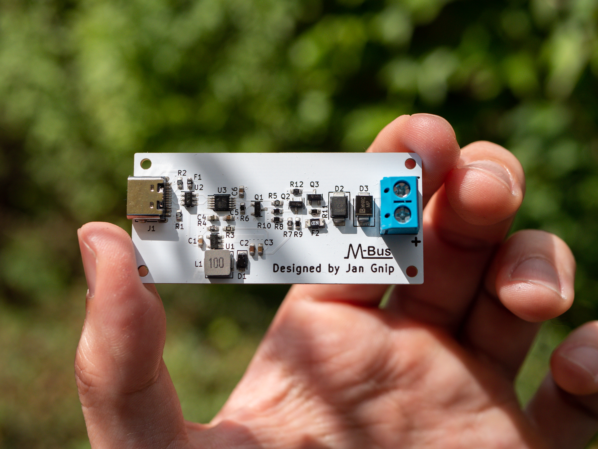
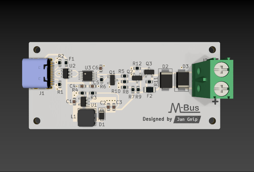
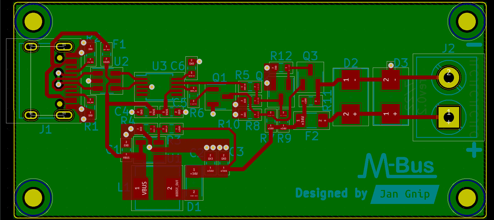
Mbus is an open-source printed circuit board by nobodyguy, from the nobodyguy/mbus_hardware repository on GitHub, published under the MIT licence. It is a 2-layer board of 59.5 × 27.2 mm with 39 parts on 27 nets, routed with 149 tracks and 24 vias.
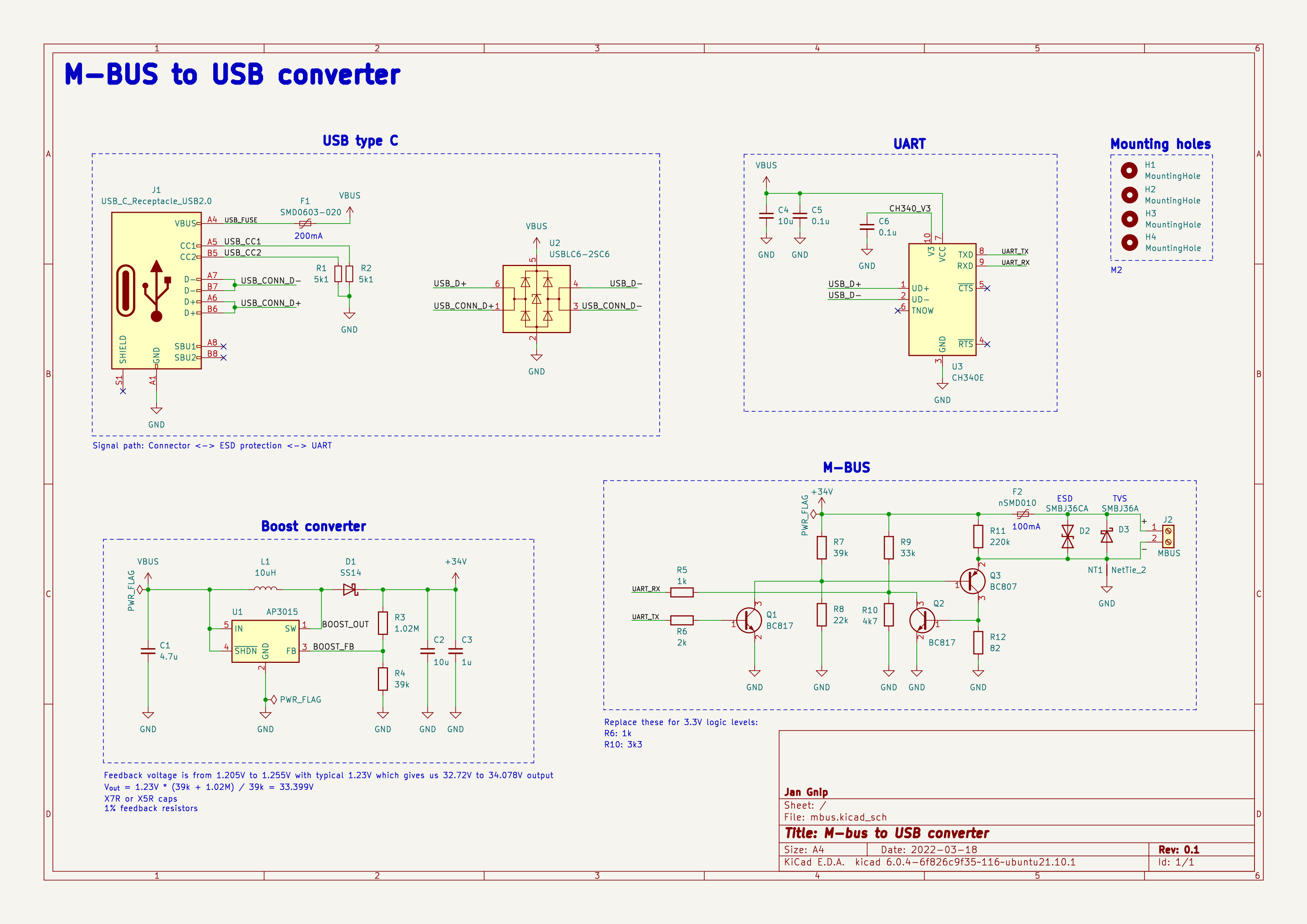
It is built around the CH340E, AP3015 and USBLC6-2SC6, with the BC817, BC807 and SMBJ36A among its other parts. Its parts include 12 resistors, 6 capacitors, 3 ICs, 3 diodes and 3 transistors.


Tested with https://github.com/ganehag/pyMeterBus library.
CH340E is 5V only IC without additional 3.3V regulator. Even its RX/TX pins are 5V. Use PL2303GL instead when CH340E is not available and change MBUS logic to 3.3V (replace R6 and R10).
| Qty | Value | Footprint | References |
|---|---|---|---|
| 4 | MountingHole | MountingHole:MountingHole_2.2mm_M2 | H1, H2, H3, H4 |
| 2 | 0.1u | Capacitor_SMD:C_0603_1608Metric | C5, C6 |
| 2 | 10u | Capacitor_SMD:C_0603_1608Metric | C2, C4 |
| 2 | 39k | Resistor_SMD:R_0603_1608Metric | R4, R7 |
| 2 | 5k1 | Resistor_SMD:R_0603_1608Metric | R1, R2 |
| 2 | BC817 | Package_TO_SOT_SMD:SOT-23 | Q1, Q2 |
| 1 | 1.02M | Resistor_SMD:R_0603_1608Metric | R3 |
| 1 | 10uH | Inductor_SMD:L_Sunlord_MWSA0518_5.4x5.2mm | L1 |
| 1 | 1k | Resistor_SMD:R_0603_1608Metric | R5 |
| 1 | 1u | Capacitor_SMD:C_0603_1608Metric | C3 |
| 1 | 220k | Resistor_SMD:R_0603_1608Metric | R11 |
| 1 | 22k | Resistor_SMD:R_0603_1608Metric | R8 |
| 1 | 2k | Resistor_SMD:R_0603_1608Metric | R6 |
| 1 | 33k | Resistor_SMD:R_0603_1608Metric | R9 |
| 1 | 4.7u | Capacitor_SMD:C_0603_1608Metric | C1 |
| 1 | 4k7 | Resistor_SMD:R_0603_1608Metric | R10 |
| 1 | 82 | Resistor_SMD:R_0603_1608Metric | R12 |
| 1 | AP3015 | Package_TO_SOT_SMD:SOT-23-5 | U1 |
| 1 | BC807 | Package_TO_SOT_SMD:SOT-23 | Q3 |
| 1 | CH340E | Package_SO:MSOP-10_3x3mm_P0.5mm | U3 |
| 1 | G*** | kibuzzard-62A19C5B | kibuzzard-62A19C5B |
| 1 | LOGO | LOGO | G*** |
| 1 | MBUS | TerminalBlock_Phoenix:TerminalBlock_Phoenix_PT-1,5-2-5.0-H_1x02_P5.00mm_Horizontal | J2 |
| 1 | NetTie_2 | NetTie:NetTie-2_SMD_Pad0.5mm | NT1 |
| 1 | SMBJ36A | Diode_SMD:D_SMB | D3 |
| 1 | SMBJ36CA | Diode_SMD:D_SMB | D2 |
| 1 | SMD0603-020 | Fuse:Fuse_0603_1608Metric | F1 |
| 1 | SS14 | Diode_SMD:D_SOD-123F | D1 |
| 1 | USBLC6-2SC6 | Package_TO_SOT_SMD:SOT-23-6 | U2 |
| 1 | USB_C_Receptacle_USB2.0 | Connector_USB:USB_C_Receptacle_HRO_TYPE-C-31-M-12 | J1 |
| 1 | nSMD010 | Fuse:Fuse_1206_3216Metric | F2 |
It measures 59.5 × 27.2 mm and has 2 copper layers, 1.6 mm thick.
39 parts, built around the CH340E, AP3015, USBLC6-2SC6 and BC817. The full list of its parts is on this page, with links to each part's symbol and footprint where PCBKit's library has them.
From the nobodyguy/mbus_hardware repository on GitHub, at the commit this page was made from: the board is mbus.kicad_pcb and its schematic mbus.kicad_sch. PCBKit opens the board in the browser, with nothing to install.
Its repository publishes it under the MIT licence: you may reuse it on that licence's terms (keep the author's notice, and for a copyleft licence share your changes alike).

tomasmcguinness/matter-esp32-mbus-adapter
An ESP32-C6 adapter board for wired M-Bus (EN 13757) meters, with firmware examples that expose meter readings to a Matter fabric over Thread.

koi-science/DI-Lambda-schematics-avr
Schematics for AVR-based DI-Lambda DITOS and UNO v1


Cuprum77/LCD_Driver
FPGA based LCD driver for cheap ST7701S displays

