Skip to the content
4 layers46 × 30 mmCan distance sensor, the printed circuit board in 3D

Can distance sensor

nlbutts/can_distance_sensor

This is a small CAN based Time-of-Flight (TOF) sensor. It determines the distance to an object and sends the resulting message on the CAN bus.

Size
46 × 30 mm
Copper layers
4
Thickness
1.6 mm
Parts
74
Nets
67
Pads
255
Tracks, vias
641, 133
Pours
2
Routed
Yes
KiCad
KiCad 9.0 (file 20241229)
Created
24 Nov 2024
Updated
28 Dec 2025

Overview

Can distance sensor is an open-source printed circuit board by nlbutts, from the nlbutts/can_distance_sensor repository on GitHub, published under the MIT licence. It is a 4-layer board of 46 × 30 mm with 74 parts on 67 nets, routed with 641 tracks and 133 vias.

It is built around the VL53L3CXV0DH/1, TPS7A0508PDBZ and L78M05ABDT-TR, with the TCA9509DGKR, USBLC6-2SC6 and SP0502BAHTG among its other parts. Its parts include 18 capacitors, 16 resistors, 8 ICs, 8 diodes and 4 connectors. It belongs with the sensors and measurement boards and the STM32 boards of this library.

Main components

8

README

README.md

I'm Not Touching You

This is a small CAN based Time-of-Flight (TOF) sensor. It determines the distance to an object and sends the resulting message on the CAN bus.

Design

The block diagram is shown below. The design consists of an input buck regulator. The regulator should be good up to 24V, but was designed to work at 12V. There is reverse battery protection, so it should handle accidentially connecting the battery up in reverse.

The buck generates 5V which is used for the CAN transceiver. The 5V is fed to two LDO's to generate 3.3V for the processor and 2.8V for the TOF sensor.

There are two status LEDs on the board. An STM32G431 processor powers everything.
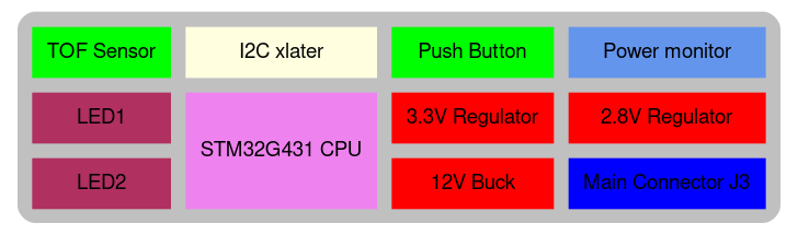
block diagram

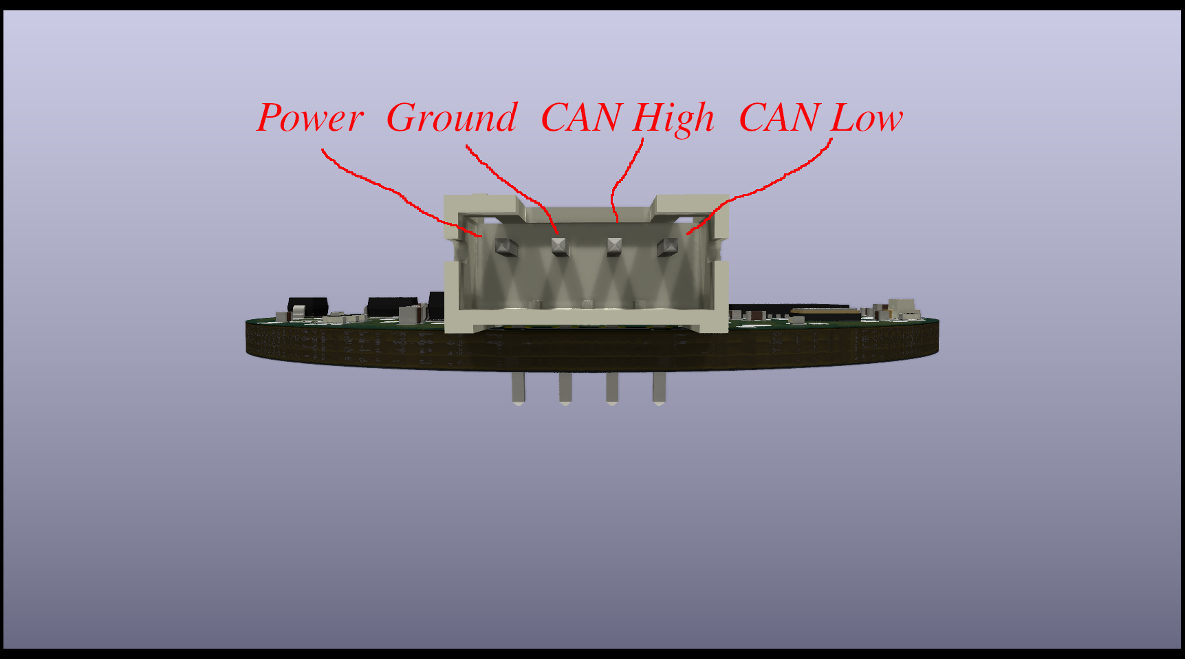
There are three user accessible connectors: Main J3:

PinUse
1Power
2Ground
3CAN High
4CAN Low

The mate is a JST PHR-4

There is a standard USB Micro B connector that connects to a PC. It enumerates as a serial port.
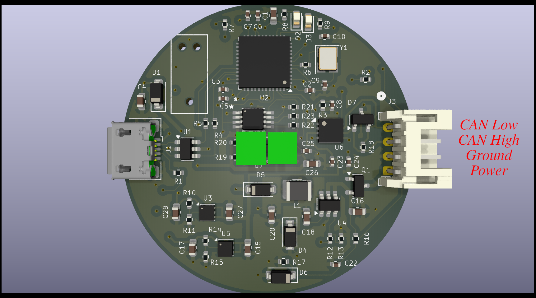
pinout1

pinout2

Software

The software uses the STM32CubeIDE to build the code. I really wanted to use CMake with the CubeMX tool, but I was having trouble getting the code to work correctly. So CudeIDE for the win.

The code is SUPER simple. It just reads the TOF sensor once every 100 ms and sends out a CAN message.

The CAN message is defined as:

ByteDefinition
1API Status
2-3distance in mm
4-5ambient Mcps
6-7signal Mcps

The API Status is the not well defined. If the value is zero, the distance is valid. The distance is in millimeters. The Ambient and Signal values are in Millions of Chips Per Second.

The CAN ID is based on the WPILib CAN interface:

CANID

Device Type is Misc (10) Manufacturer is 20 API Class is Status (5) API Index is 0 Device Number is currently 0 (need to figure out how to have several of these on the bus)

SWD Debug

It is assumed you are using a JLink and it is installed in /opt/SEGGER/JLink In the scripts directory:

  1. Run gdbstart.sh in one terminal
  2. Run debug.sh in other terminal. You now have the full power of GDB at your literial finger tips

Firmware upgrade

There is no ability to upgrade the firmware right now. It will be fixed in future PCB rev. Currently you have to JTAG/SWD the firmware.

Potential other parts

STM32G0: https://jlcpcb.com/partdetail/STMicroelectronics-STM32G0B1CBT6/C2847904 Can we use a M0???

Parts

74
QtyValueFootprintReferences
14TestPointTestPoint:TestPoint_Pad_D1.0mmTP1, TP2, TP3, TP4, TP5, TP6, TP7, TP8, TP9, TP10, TP11, TP12, TP13, TP14
60.1uCapacitor_SMD:C_0402_1005MetricC2, C3, C8, C23, C24, C25
64.7uCapacitor_SMD:C_0603_1608MetricC1, C15, C17, C26, C27, C28
310KResistor_SMD:R_0402_1005MetricR19, R20, R22
3SP0502BAHTPackage_TO_SOT_SMD:SOT-23D7, D8, D9
2100kResistor_SMD:R_0402_1005MetricR3, R16
210uCapacitor_SMD:C_0603_1608MetricC16, C20
215pCapacitor_SMD:C_0402_1005MetricC9, C10
21KResistor_SMD:R_0402_1005MetricR2, R6
22.2kResistor_SMD:R_0402_1005MetricR21, R23
222Resistor_SMD:R_0402_1005MetricR4, R5
2330Resistor_SMD:R_0402_1005MetricR8, R9
2D_SchottkyDiode_SMD:D_SOD-123D1, D5
2LEDLED_SMD:LED_0603_1608MetricD2, D3
2MountingHoleMountingHole:MountingHole_2.2mm_M2H1, H2
2TPS7A0508PDBZPackage_TO_SOT_SMD:SOT-23U3, U4
110kResistor_SMD:R_0402_1005MetricR17
1120Resistor_SMD:R_0402_1005MetricR18
11uCapacitor_SMD:C_0402_1005MetricC22
12.2uCapacitor_SMD:C_0603_1608MetricC4
14.7kResistor_SMD:R_0402_1005MetricR7
1AO3401APackage_TO_SOT_SMD:SOT-23Q2
1Conn_01x04Connector_JST:JST_PH_S4B-PH-K_1x04_P2.00mm_HorizontalJ3
1Conn_01x06Connector_JST:JST_PH_S6B-PH-K_1x06_P2.00mm_HorizontalJ4
1Conn_ARM_JTAG_SWD_10Connector:Tag-Connect_TC2050-IDC-NL_2x05_P1.27mm_Vertical_with_bottom_clipJ2
1Crystal_GND24Crystal:Crystal_SMD_3225-4Pin_3.2x2.5mmY1
1D_ZenerDiode_SMD:D_SOD-123D6
1L78M05ABDT-TRfootprints:VREG_L78M05ABDT-TRU2
1PTS645SK50SMTR92LFSfootprints:PTS645SK50SMTR92LFS_CNKSW1
1STM32G0B1KBUxPackage_DFN_QFN:QFN-32-1EP_5x5mm_P0.5mm_EP3.45x3.45mmU9
1SolderJumper_3_Bridged12Jumper:SolderJumper-3_P1.3mm_Bridged2Bar12_RoundedPad1.0x1.5mm_NumberLabelsJP1
1TCA9509DGKRfootprints:DGK8U8
1TCAN1044A-Q1Package_SON:VSON-8-1EP_3x3mm_P0.65mm_EP1.6x2.4mmU6
1USBLC6-2SC6Package_TO_SOT_SMD:SOT-23-6U1
1USB_C_Receptaclefootprints:CONN_105450-0101_MOLJ5
1VL53L3CXV0DH/1footprints:LGA12_STMU7

Similar boards

  • 2 layersNavigator, the printed circuit board in 3D

    Navigator

    PhilipMcGaw/robot-NautiPi

    NautiPi is the physical hardware and embedded-project repository for the robot projects. It contains electronics, PCB and KiCad work, Arduino projects, component records, mechanical references, photographs, and retained…

    25 parts
  • 4 layers84 × 49 mmBackPorch, the printed circuit board in 3D

    BackPorch

    nlbutts/Foyers

    These are similar to the SWYFT CAN wiring devices

    80 partsMIT
  • 2 layers83.6 × 107.3 mmShield stm2025, the printed circuit board in 3D

    Shield stm2025

    Rami-Troudi/Electrique-Eurobot-IEEE-INSAT-2026

    Repo for my electrical work for the Eurobot competition

    66 parts1
  • 2 layers20 × 20 mmLightSensorPCB, the printed circuit board in 3D

    LightSensorPCB

    dwynnychuk/SmartSmoker

    Upgrades for Traeger to add smart capability

    18 parts
  • 4 layers25 × 25 mmDistance, the printed circuit board in 3D

    Distance

    sean618/MakerTiles

    Modular STM32 electronic-tile system: hardware, firmware, the MicroBus + Field Protocol stack, and a Python daemon.

    20 partsMIT
  • 4 layers99.8 × 94.6 mmStar tracker card, the printed circuit board in 3D

    Star tracker card

    oresat/oresat-star-tracker-hardware

    Hardware for OreSat's Star Tracker

    263 parts49
  • 4 layers46.8 × 64.2 mmCommodore 7, the printed circuit board in 3D

    Commodore 7

    parsa-novin/UGA-IREC

    48 parts2

Questions

How big is the Can distance sensor PCB?

It measures 46 × 30 mm and has 4 copper layers, 1.6 mm thick.

What parts does the Can distance sensor use?

74 parts, built around the VL53L3CXV0DH/1, TPS7A0508PDBZ, L78M05ABDT-TR and TCA9509DGKR. The full list of its parts is on this page, with links to each part's symbol and footprint where PCBKit's library has them.

Where can I download the Can distance sensor KiCad files?

From the nlbutts/can_distance_sensor repository on GitHub, at the commit this page was made from: the board is electronics/can_distance_sensor.kicad_pcb and its schematic electronics/Can.kicad_sch. PCBKit opens the board in the browser, with nothing to install.

Can I use the Can distance sensor design in my own project?

Its repository publishes it under the MIT licence: you may reuse it on that licence's terms (keep the author's notice, and for a copyleft licence share your changes alike).