2 layers46 × 38 mm

 nlbutts/Foyers
These are similar to the SWYFT CAN wiring devices
BackPorch is an open-source printed circuit board by nlbutts, from the nlbutts/Foyers repository on GitHub, published under the MIT licence. It is a 4-layer board of 84 × 49 mm with 80 parts on 64 nets, routed with 684 tracks and 132 vias.
It is built around the L78M05ABDT-TR, USBLC6-2SC6 and XC6206P332MR-G, with the SP0502BAHTG, RJ45 and JS202011SCQN among its other parts. Its parts include 15 resistors, 14 capacitors, 14 diodes, 9 connectors and 6 ICs. It belongs with the STM32 boards of this library.


The Foyers/BackPorch system is an STM32-based hardware ecosystem designed for FRC robot sensing and control, featuring CAN communication with a built-in bootloader.
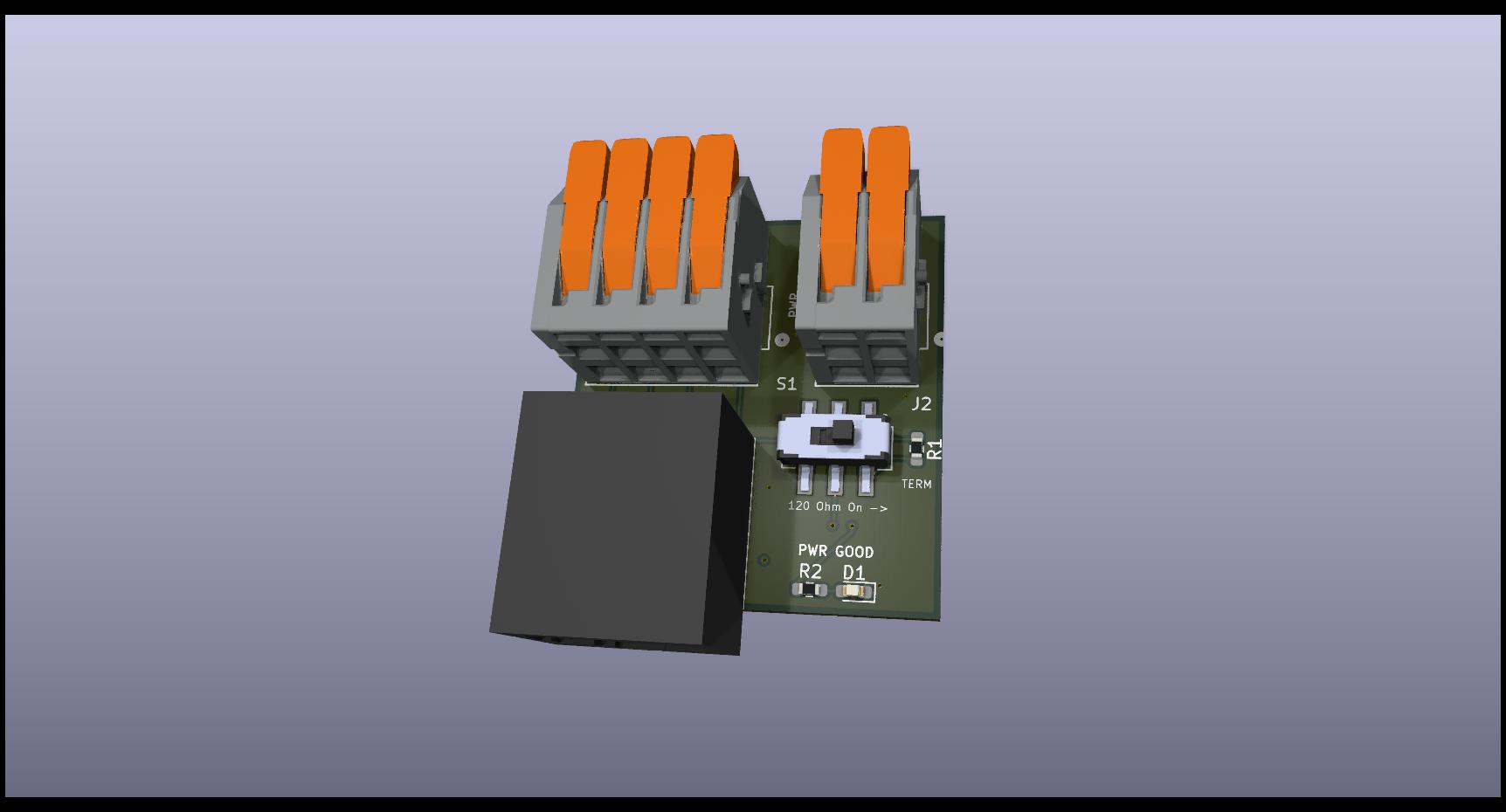
The Foyer board serves as the primary distribution point for the system.
The BackPorch is the central controller board, based on the STM32G0B1 microcontroller. It handles high-level CAN communication, sensor aggregation, and basic power management.
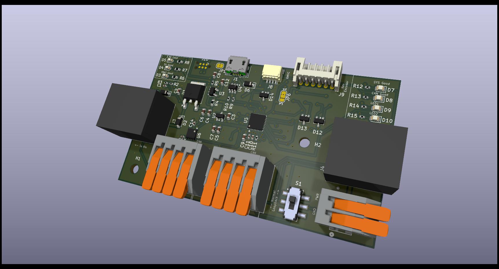
| Ref | Type | Function | Mating Part |
|---|---|---|---|
| J4 | RJ45 | CAN Bus | Standard RJ45 Plug |
| J9 | JST PH 6-pin | Rev Through Bore Encoder | JST PHR-6 |
| J10 | USB Micro B | Power / Debug | Standard Micro-USB |
| J1/J2 | Wago 2601 | Power Input (VBAT/GND) | 24-16 AWG Wire |
| J3 | Wago 2601 | Motor Output | 24-16 AWG Wire |
| J6 | Tag-Connect | SWD Programming | TC2030-IDC |
J4 (RJ45) CAN Pinout:
J9 (Rev Through Bore Encoder) Pinout: Compatible with the REV Through Bore Encoder.
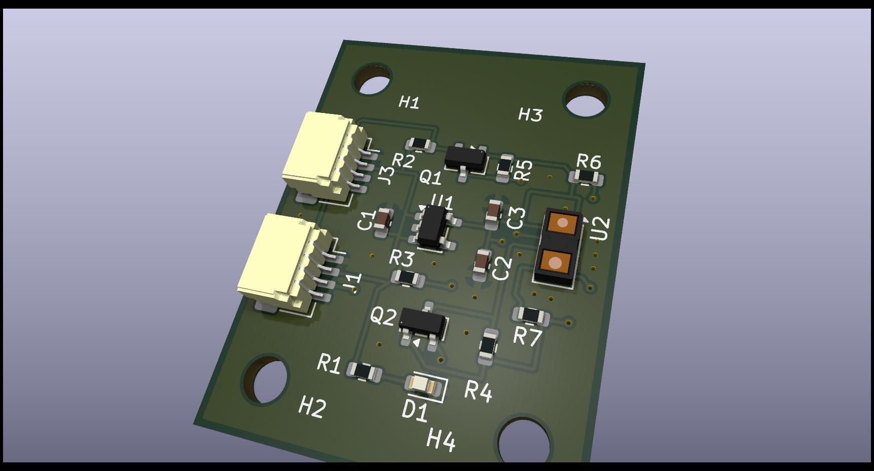
A compact Time-of-Flight (ToF) distance sensor breakout designed to interface with the BackPorch.
This project uses the official STM32 development workflow:
.ioc files in the software/backporch or software/bootloader directories to modify the hardware configuration.arm-none-eabi-gcc is installed and in your PATH.CMake workflow provided by the extension.The software/can_mon/bp_debug.py program is a multi-purpose Python utility for interacting with the hardware over CAN.
.bin files to a target device ID and commit them to flash.python software/can_mon/bp_debug.pyNote: Requires python-can and tkinter libraries. Ensure your CAN adapter is configured (default: SLSAN on COM5).
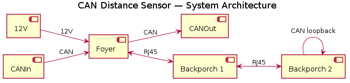
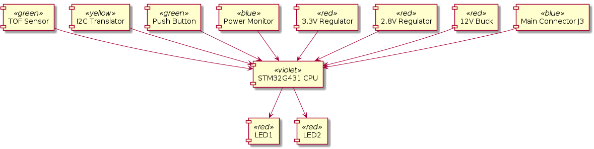
The system follows a modular architecture where multiple sensor nodes (Foyers) communicate with the BackPorch controller over a shared CAN bus, which then interfaces with the Robot Controller.
 These are similar to the SWYFT CAN wiring devices
| Qty | Value | Footprint | References |
|---|---|---|---|
| 13 | TestPoint | TestPoint:TestPoint_Pad_D1.0mm | TP1, TP2, TP3, TP4, TP5, TP6, TP7, TP8, TP9, TP10, TP11, TP12, TP13 |
| 4 | 0.1u | Capacitor_SMD:C_0402_1005Metric | C10, C11, C13, C14 |
| 4 | 4.7u | Capacitor_SMD:C_0603_1608Metric | C3, C5, C7, C9 |
| 4 | 49.9 | Resistor_SMD:R_0402_1005Metric | R12, R13, R14, R15 |
| 4 | LED | LED_SMD:LED_0805_2012Metric | D7, D8, D9, D10 |
| 4 | SP0502BAHT | Package_TO_SOT_SMD:SOT-23 | D11, D12, D13, D14 |
| 4 | SolderJumper_3_Bridged12 | Jumper:SolderJumper-3_P1.3mm_Bridged12_RoundedPad1.0x1.5mm | JP2, JP3, JP4, JP5 |
| 3 | 10u | Capacitor_SMD:C_0603_1608Metric | C2, C4, C6 |
| 3 | LED | LED_SMD:LED_0603_1608Metric | D3, D4, D5 |
| 2 | 1k | Resistor_SMD:R_0402_1005Metric | R3, R5 |
| 2 | 2.2u | Capacitor_SMD:C_0603_1608Metric | C8, C12 |
| 2 | 22 | Resistor_SMD:R_0402_1005Metric | R9, R10 |
| 2 | 2601-1104 | LocalFootprints:CONN4_2601-1104_WAG | J6, J7 |
| 2 | 330 | Resistor_SMD:R_0603_1608Metric | R7, R8 |
| 2 | D_Schottky | Diode_SMD:D_SOD-123 | D2, D6 |
| 2 | MountingHole | MountingHole:MountingHole_3.2mm_M3_DIN965 | H1, H2 |
| 2 | RJ45 | LocalFootprints:AMPHENOL_54602-908LF | J3, J4 |
| 1 | 1 | Resistor_SMD:R_0603_1608Metric | R4 |
| 1 | 10k | Resistor_SMD:R_0402_1005Metric | R2 |
| 1 | 1u | Capacitor_SMD:C_0402_1005Metric | C1 |
| 1 | 2601-1102 | LocalFootprints:CONN2_2601-1102_WAG | J5 |
| 1 | 4.7k | Resistor_SMD:R_0402_1005Metric | R11 |
| 1 | 49.9 | Resistor_SMD:R_0805_2012Metric | R1 |
| 1 | 680 | Resistor_SMD:R_0603_1608Metric | R6 |
| 1 | Conn_01x04 | Connector_JST:JST_SH_SM04B-SRSS-TB_1x04-1MP_P1.00mm_Horizontal | J8 |
| 1 | Conn_01x06 | Connector_JST:JST_PH_S6B-PH-K_1x06_P2.00mm_Horizontal | J9 |
| 1 | Conn_ARM_SWD_TagConnect_TC2030-NL | Connector:Tag-Connect_TC2030-IDC-NL_2x03_P1.27mm_Vertical | J10 |
| 1 | D_Zener | Diode_SMD:D_SOD-123 | D1 |
| 1 | INA180A1 | Package_TO_SOT_SMD:SOT-23-5 | U3 |
| 1 | JS202011SCQN | LocalFootprints:SW_JS202011SCQN | S1 |
| 1 | L78M05ABDT-TR | Package_TO_SOT_SMD:TO-252-2 | U1 |
| 1 | STM32G0B1KBUx | Package_DFN_QFN:QFN-32-1EP_5x5mm_P0.5mm_EP3.45x3.45mm | U5 |
| 1 | SolderJumper_2_Bridged | Jumper:SolderJumper-2_P1.3mm_Bridged2Bar_RoundedPad1.0x1.5mm | JP1 |
| 1 | SolderJumper_3_Bridged12 | Jumper:SolderJumper-3_P1.3mm_Bridged2Bar12_RoundedPad1.0x1.5mm_NumberLabels | JP6 |
| 1 | TCAN1044A-Q1 | Package_SON:VSON-8-1EP_3x3mm_P0.65mm_EP1.6x2.4mm | U6 |
| 1 | USBLC6-2SC6 | Package_TO_SOT_SMD:SOT-23-6 | U4 |
| 1 | USB_B_Micro | Connector_USB:USB_Micro-B_Amphenol_10118193-0001LF_Horizontal | J1 |
| 1 | XC6206P332MR-G | Package_TO_SOT_SMD:SOT-23 | U2 |

nlbutts/can_distance_sensor
This is a small CAN based Time-of-Flight (TOF) sensor. It determines the distance to an object and sends the resulting message on the CAN bus.


WinstonHar/ENCE_3231_Winston
Microcontroller project code repository
It measures 84 × 49 mm and has 4 copper layers, 1.6 mm thick.
80 parts, built around the L78M05ABDT-TR, USBLC6-2SC6, XC6206P332MR-G and SP0502BAHTG. The full list of its parts is on this page, with links to each part's symbol and footprint where PCBKit's library has them.
From the nlbutts/Foyers repository on GitHub, at the commit this page was made from: the board is electronics/BackPorch/BackPorch.kicad_pcb and its schematic electronics/BackPorch/BackPorch.kicad_sch. PCBKit opens the board in the browser, with nothing to install.
Its repository publishes it under the MIT licence: you may reuse it on that licence's terms (keep the author's notice, and for a copyleft licence share your changes alike).
