
2 layers67 × 61.6 mm
5V regulated power supply pcbdesign
niyathiarun/Basic-PCB-Projects
Beginner PCB design collection built in KiCad — includes 5V Regulated Power Supply, 555 Astable Multivibrator, and BJT Astable Multivibrator circuits.
14 parts3
 niyathiarun/Basic-PCB-Projects3
Beginner PCB design collection built in KiCad — includes 5V Regulated Power Supply, 555 Astable Multivibrator, and BJT Astable Multivibrator circuits.
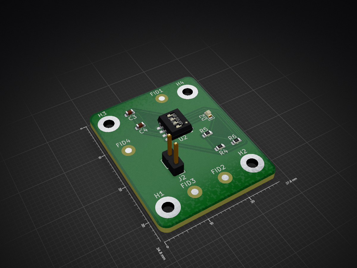
555 Astable multivibrator is an open-source printed circuit board by niyathiarun, from the niyathiarun/Basic-PCB-Projects repository on GitHub. It is a 2-layer board of 27.8 × 34.8 mm with 16 parts on 6 nets, routed with 83 tracks and 0 vias.
It is built around the NE555P. Its parts include 3 resistors, 2 capacitors, 1 IC, 1 diode and 1 connector.
This repository showcases three foundational PCB design projects created using KiCad, focusing on analog and mixed-signal circuit design for beginners in electronics.
Each project demonstrates schematic design, PCB layout, and practical circuit understanding.
This project implements a transformer-based 5V DC regulated power supply designed using the LM7805 voltage regulator IC.
It converts 230V AC mains into a stable 5V DC output, suitable for powering logic circuits, sensors, and microcontrollers.
🔧 Circuit Overview
🧠 Key Features
📂 Files Included
5V-Regulated-Power-Supply.kicad_sch – KiCad schematic file5V-Regulated-Power-Supply.kicad_pcb – PCB layout file5V-regulated-power-supply-schematic.png – Circuit schematicpcb_layout.png – PCB top viewBOM.csv – Bill of Materials🧾 Bill of Materials
| Component | Value / Type | Quantity | Description |
|---|---|---|---|
| T1 | 230V/12V Step-down Transformer | 1 | Power isolation and voltage reduction |
| D1–D4 | 1N4007 | 4 | Rectifier diodes |
| C1 | 470µF / 25V | 1 | Filter capacitor |
| C2, C3 | 0.1µF | 2 | Noise filter capacitors |
| U1 | LM7805 | 1 | 5V voltage regulator |
| R1 | 150Ω | 1 | LED current limiter |
| D5 | LED (Red) | 1 | Power ON indicator |
| F1 | Fuse | 1 | Overcurrent protection |
| J1, J2 | Connectors | 2 | Input and output terminals |
⚡ Applications
This project demonstrates the use of the NE555 timer IC configured in astable mode to generate a continuous square wave output.
The circuit is one of the simplest ways to produce a periodic ON/OFF signal used for LED blinking, clock pulses, or PWM control.
🔧 Circuit Overview
→ Approximate frequency: 720 Hz (LED blinks fast; values can be modified for slower blinking).
🧠 Key Features
📂 Files Included
555-timer.kicad_sch – Schematic design file555-timer.kicad_pcb – PCB layout file555-timer-schematic.png – Circuit diagrampcb_layout.png – PCB layout imageBOM.csv – Bill of Materials🧾 Bill of Materials
| Component | Value / Type | Quantity | Description |
|---|---|---|---|
| U2 | NE555P Timer IC | 1 | Generates pulse signal |
| R4 | 10kΩ | 1 | Timing resistor 1 |
| R5 | 10kΩ | 1 | Timing resistor 2 |
| R6 | 1kΩ | 1 | Current limiting resistor for LED |
| C3 | 0.1µF | 1 | Timing capacitor |
| C4 | 0.01µF | 1 | Control voltage stabilizer |
| D2 | LED | 1 | Output indicator |
| PWR_FLAG | — | 1 | Power supply indicator |
⚡ Applications
A transistor-based astable multivibrator that produces continuous oscillating output without using ICs — ideal for understanding the basic principles of transistor switching.
🔧 Circuit Overview -The circuit consists of two NPN transistors(2N3904), each driving an LED in its collector branch, and connected in a cross-coupled configuration using two capacitors (220 µF each) between the collector of each transistor and the base of the other. -Two pairs of resistors control both the current through the LEDs (1 kΩ at each collector) and the charging rate of the capacitors (5 kΩ at each base). -When one transistor turns on, it pulls its collector low and forward-biases the opposite transistor’s base through the coupling capacitor, turning it off. -This alternating action creates a continuous oscillation: while one LED is ON, the other is OFF, and they toggle back and forth automatically. -The entire circuit is powered by a single 3.7V power supply.
Key Features
Files Included
BJT-Astable-Multivibrator.kicad_sch-shematic design fileBJT-Astable-Multivibrator.kicad_pcb-PCB layout fileschematic.png-Circuit diagrampcb_layout.png-PCB layout imageBOM.csv-Bill of materials🧾 Bill of Materials
| Component | Value / Type | Quantity | Description |
|---|---|---|---|
| Q1 | Q2 | 2N3904 NPN Transistors | |
| R1 | 1kΩ | 1 | control the charging and discharging of capacitors and base currents of the transistors |
| R2 | 5kΩ | 1 | control the charging and discharging of capacitors and base currents of the transistors |
| R3 | 5kΩ | 1 | control the charging and discharging of capacitors and base currents of the transistors |
| R4 | 1kΩ | 1 | control the charging and discharging of capacitors and base currents of the transistors |
| C1 | C2 | 220uF | |
| D1 | D2 | LED |
Applications
Basic-PCB-Projects/ ┣ README.md ┣ 5V-Regulated-Power-Supply/ ┣ 555-Astable-Multivibrator/ ┗ BJT-Astable-Multivibrator/
Niyathi Arun Kurthkoti
ECE Student | Aspiring Embedded & PCB Design Engineer
| Qty | Value | Footprint | References |
|---|---|---|---|
| 4 | Fiducial | Fiducial:Fiducial_1.5mm_Mask3mm | FID1, FID2, FID3, FID4 |
| 4 | MH | MountingHole:MountingHole_2.5mm_Pad | H1, H2, H3, H4 |
| 2 | 10K | Resistor_SMD:R_0603_1608Metric | R4, R5 |
| 1 | 0.01uF | Capacitor_SMD:C_0603_1608Metric | C4 |
| 1 | 0.1uF | Capacitor_SMD:C_0603_1608Metric | C3 |
| 1 | 1K | Resistor_SMD:R_0603_1608Metric | R6 |
| 1 | LED | LED_SMD:LED_0603_1608Metric | D2 |
| 1 | NE555P | Package_SO:SOP-8_3.76x4.96mm_P1.27mm | U2 |
| 1 | POWER INPUT | Connector_PinHeader_2.54mm:PinHeader_1x02_P2.54mm_Vertical | J2 |
niyathiarun/Basic-PCB-Projects
Beginner PCB design collection built in KiCad — includes 5V Regulated Power Supply, 555 Astable Multivibrator, and BJT Astable Multivibrator circuits.

baldengineer/bit-preserve
Project for capturing vintage, classic, aka old computer schematics in KiCad.

The-Invent0r/8-bit-Computer-PCB
These are the KiCAD files for my 8-Bit Computer.

DarcyJProjects/touchtone555
An open-source DIY, NE555-based analogue synthesizer - play notes with a stylus


benjiaomodular/SynthCard
I designed this project with the help of PCBWay. You can get a copy of these cards through the PCBWay Shared Projects page.

fortinsylvain/MyCpu
Home brew CPU Hardware with 1-bit ALU implementation using 74LSxx, a micro-code and assembler coded in C#.

hackup/C128Diag
Replica of the Commodore C128 Diagnostic Test cartridge Assy No. 325093-01.
It measures 27.8 × 34.8 mm and has 2 copper layers, 1.6 mm thick.
16 parts, built around the NE555P. The full list of its parts is on this page, with links to each part's symbol and footprint where PCBKit's library has them.
From the niyathiarun/Basic-PCB-Projects repository on GitHub, at the commit this page was made from: the board is project 2/555 Astable multivibrator.kicad_pcb and its schematic project 1/5V regulated power supply shematic.kicad_sch. PCBKit opens the board in the browser, with nothing to install.
Its repository states no licence, so its author keeps all rights: ask niyathiarun before reusing the design.