2 layers100 × 77.5 mm
 nitsu121/SecurityPCB
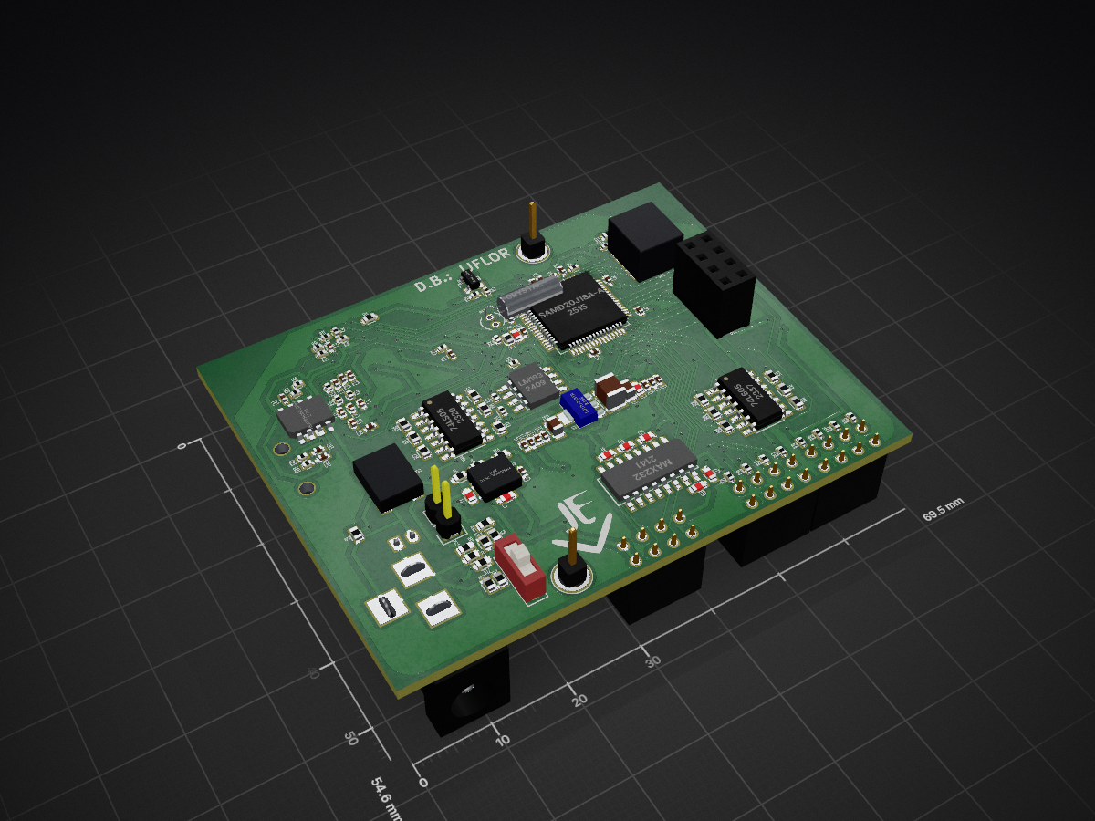
Wireless Xciever is an open-source printed circuit board by nitsu121, from the nitsu121/SecurityPCB repository on GitHub. It is a 2-layer board of 69.5 × 54.6 mm with 147 parts on 124 nets, routed with 1,998 tracks and 194 vias.
It is built around the MAX232N, 74LS05P-E and LD1117S33TR(MS). Its parts include 60 resistors, 47 capacitors, 10 ICs, 8 connectors and 7 diodes. It belongs with the SAM D and SAM boards of this library.


| Qty | Value | Footprint | References |
|---|---|---|---|
| 17 | 0.1UF | Capacitors_SMD:C_0402 | C20, C21, C22, C23, C24, C26, C27, C31, C40, C41, C42, C43, C44, C45, C46, C47 +1 |
| 15 | 10K 0HM | Resistors_SMD:R_0402 | R16, R17, R19, R20, R21, R24, R26, R27, R28, R29, R38, R39, R46, R47, R55 |
| 12 | 350 0HM | Resistors_SMD:R_0603 | R40, R41, R42, R43, R44, R45, R48, R49, R50, R51, R52, R53 |
| 10 | 0 0HM | Resistors_SMD:R_0603 | R1, R2, R3, R4, R5, R8, R9, R11, R12, R15 |
| 8 | 10K OHM | Resistors_SMD:R_0402 | R22, R23, R30, R33, R34, R56, R57, R58 |
| 5 | 1UF | Capacitors_SMD:C_0603 | C15, C16, C17, C18, C19 |
| 4 | 1uF | Capacitors_SMD:C_0402 | C32, C33, C36, C38 |
| 4 | CONN_02X04 | Connect:My_0.1_5X2RowConnector | P2, P3, P4, P6 |
| 4 | MY_LED_RABG | LEDs:MY_RGB_LED | D9, D10, D11, D12 |
| 4 | SW_PUSH | Buttons_Switches_SMD:SW_SPST_EVPBF | SW2, SW3, SW4, SW5 |
| 3 | 0.01UF | Capacitors_SMD:C_0402 | C8, C13, C14 |
| 3 | 10UF | Capacitors_SMD:C_0402 | C11, C12, C25 |
| 2 | 0 0HM | Resistors_SMD:R_0402 | R18, R54 |
| 2 | 100K OHM | Resistors_SMD:R_0402 | R35, R36 |
| 2 | 100nF | Capacitors_SMD:C_0402 | C34, C39 |
| 2 | 10UF | Capacitors_SMD:C_0603 | C5, C28 |
| 2 | 1K OHM | Resistors_SMD:R_0402 | R59, R60 |
| 2 | 1pin | Connect:1pin | , |
| 2 | 2K OHM | Resistors_SMD:R_0402 | R31, R32 |
| 2 | 4.7UF | Capacitors_SMD:C_0603 | C1, C3 |
| 2 | 4.7uF | Capacitors_SMD:C_0402 | C35, C37 |
| 2 | 47UF | Capacitors_SMD:C_0805 | C4, C10 |
| 2 | 74LS05 | Housings_SOIC:SOIC-14_3.9x8.7mm_Pitch1.27mm | U6, U7 |
| 2 | ? | Capacitors_SMD:C_0402 | C29, C30 |
| 2 | Led_Small | Diodes_SMD:MY_LED-1.6X0.8 | D7, D8 |
| 1 | Labels:MyLogo | ||
| 1 | 14.3K 0HM | Resistors_SMD:R_0603 | R7 |
| 1 | 1M 0HM | Resistors_SMD:R_0603 | R6 |
| 1 | 1UF | Capacitors_SMD:C_0402 | C6 |
| 1 | 2.2K 0HM | Resistors_SMD:R_0402 | R25 |
| 1 | 220UF | Capacitors_SMD:C_1210 | C9 |
| 1 | 22PF | Capacitors_SMD:C_0402 | C2 |
| 1 | 390K OHM | Resistors_SMD:R_0402 | R37 |
| 1 | 75K 0HM | Resistors_SMD:R_0603 | R10 |
| 1 | ? 0HM | Resistors_SMD:R_0402 | R14 |
| 1 | ? 0HM | Resistors_SMD:R_0603 | R13 |
| 1 | AT30TSE758_TEMP_SENSOR | Housings_SOIC:SOIC-8_3.9x4.9mm_Pitch1.27mm | U5 |
| 1 | BARREL_JACK | Connect:BARREL_JACK | CON1 |
| 1 | Battery | Connectors_JST_PH:Connectors_JST_B2B-PH-K | BT1 |
| 1 | CONN_01X02 | Pin_Headers:Pin_Header_Straight_1x02 | P1 |
| 1 | CONN_01X03 | Connect:MY_AUDIO_JACK | P7 |
| 1 | CONN_02X05 | Connect:My_Programmer_Connector_5x2row | P5 |
| 1 | Crystal | Crystals:Crystal_Round_Vertical_3mm | Y1 |
| 1 | Darl_NPN | TO_SOT_Packages_SMD:SOT-23 | Q2 |
| 1 | Diode_Bridge | Opto-Devices:MY_NEW_FULL_BRIDGE_RECTIFIER | D3 |
| 1 | HEADPHONE_DRIVER_TPA0211 | SMD_Packages:MSOP-8-EXPOSED-PAD | U10 |
| 1 | INDUCTOR | Resistors_SMD:R_0603 | L2 |
| 1 | LD1117S33TR | TO_SOT_Packages_SMD:SOT89-3_Housing | U2 |
| 1 | LM193 | SMD_Packages:SOIC-8-N | U9 |
| 1 | MAX232 | SMD_Packages:SO-16-N | U3 |
| 1 | MIC | Opto-Devices:MY_MIC | U8 |
| 1 | MPM3510A_SWITCHING_REGULATOR | Power_Integrations:MPM3510A | U1 |
| 1 | OPTO_NPN | TO_SOT_Packages_SMD:My_light_sensor_4X2 | Q1 |
| 1 | SAMD20J18A-A | Housings_QFP:LQFP-64_10x10mm_Pitch0.5mm | U4 |
| 1 | SPEAKER | Buzzers_Beepers:My_Buzzer_12.8X12.8 | SP1 |
| 1 | Switch_SPDT_x2 | Buttons_Switches_ThroughHole:SW_Micro_SPST | SW1 |
| 1 | UG-2832HSWEG04-OLED_DISP | Connect:MY_OLED_UG-2832hsweg04 | S1 |
It measures 69.5 × 54.6 mm and has 2 copper layers, 1.6 mm thick.
147 parts, built around the MAX232N, 74LS05P-E and LD1117S33TR(MS). The full list of its parts is on this page, with links to each part's symbol and footprint where PCBKit's library has them.
From the nitsu121/SecurityPCB repository on GitHub, at the commit this page was made from: the board is Wireless_Xciever.kicad_pcb. PCBKit opens the board in the browser, with nothing to install.
Its repository states no licence, so its author keeps all rights: ask nitsu121 before reusing the design.

transistorfet/computie
A collection of 68k computer projects, including a unix-like operating system written in C that runs on them


raymondh2/CompaqPortableIII
Current PCB Memory Expansion board layout is untested. The backplane for the expansion cards is tested and working.

barberd/coco9511pak
This board is a cartridge for the Tandy Radio Shack TRS-80 Color Computer (CoCo), an 8 bit computer produced between 1980 and 1991. It provides an Arithmetic Processor Unit (APU), the AMD 9511, to the CoCo.


