2 layers43.9 × 27.7 mm

 nirvaankohli/MORPH.00
6 button + a Knob macropad with a screen panel above it. Its entire function changes depending on the app opened.
MORPH.00 is an open-source printed circuit board by nirvaankohli, from the nirvaankohli/MORPH.00 repository on GitHub. It is a 2-layer board of 222.5 × 97.5 mm with 19 parts on 28 nets, routed with 210 tracks and 10 vias.
Its parts include 7 switches, 4 resistors, 2 capacitors and 1 IC. It belongs with the keyboards and input boards of this library.
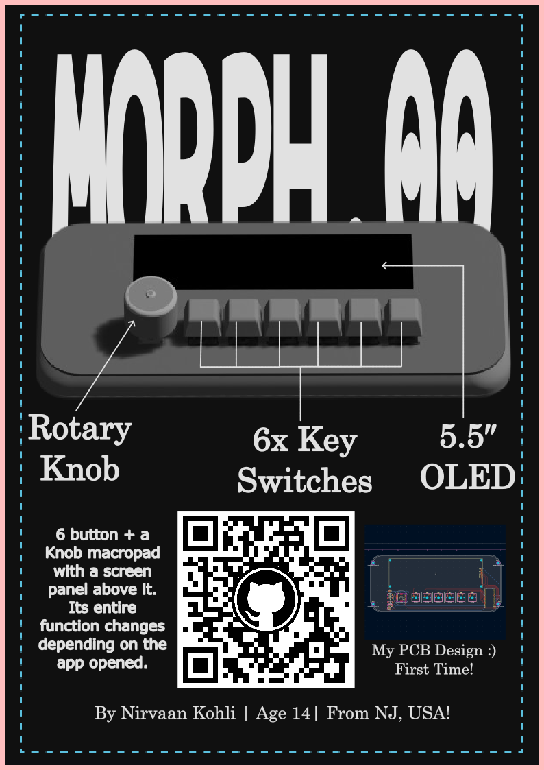
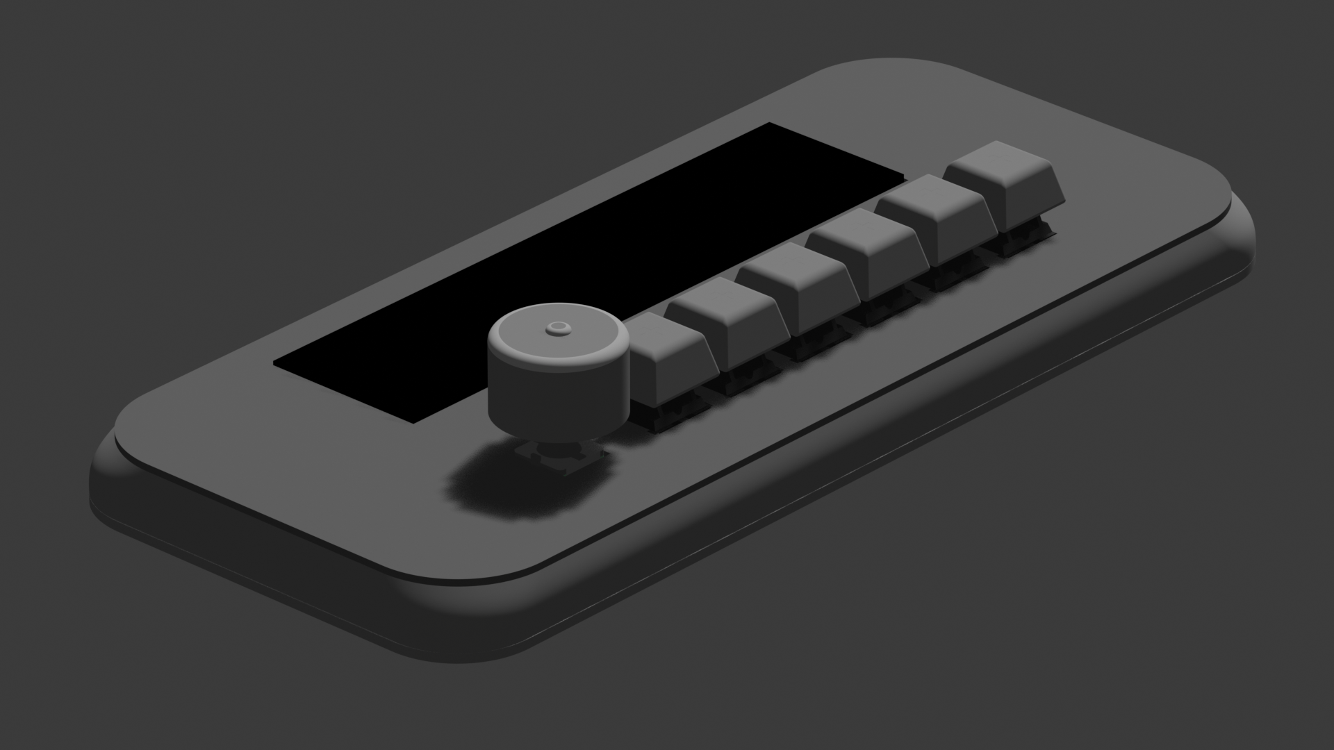
MORPH.00 is a keyboard with 6 key switches and a rotary encoder that can change(morph their function). It also has an OLED to display each key or encoder's function at any given time. It is powered by the RP2040!
When I initially found about fallout, I knew it was an one in a lifetime opportunity. I also knew that I did not know anything about hardware. So I looked online and on youtube and decided that a macropad was perfect for me. After a few days of brainstorming, I decided to settle for the best balance between challenging and easy(this project). Also it was pretty cool, cus like who would not want a keyboard that can change functions based on the app you are on to make work less repetitive. The use for this is legitimate because I can think of so many times in a day I press the same 6 button when in app. This would be really useful for myself, and that's why I chose to build it. Also a keyboard with a screen is rlly cool.
Looking back, this project was filled with a lot of firsts. I also had so much fun. Like who knew how relaxing some parts could be and how enraging others could be. Anyways, I learned my first real CAD software, onshape. I will definitely be using it in VEX Robotics as most of our team's CAD team seniored out. It took me some time to get comfortable but it is pretty cool. It was also my first time with KiCad. Making the schematic was interesting, pcb routing was so relaxing, but the errors sadly was not.
The keyboard is powered by a RP2040 on a KB2040 Microcontroller running CircuitPython with many adafruit libraries. This is stuffed on the bottom-right side of the pcb board/keyboard and is the reason for it's goofy shape and proportions.
The six switches are Cherry MXs, the rotary encoder an EC11 Rotary Encoder, and the OLED a 5.5 Inch 256x64 display. There is also a part of this project on the host computer that sends info like key, encoder, or OLED changes to the keyboard.
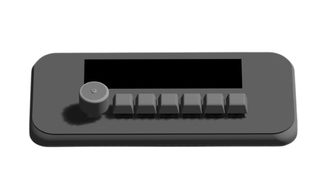
CAD was a very infuriating experience if I may add.
This is my final schematic
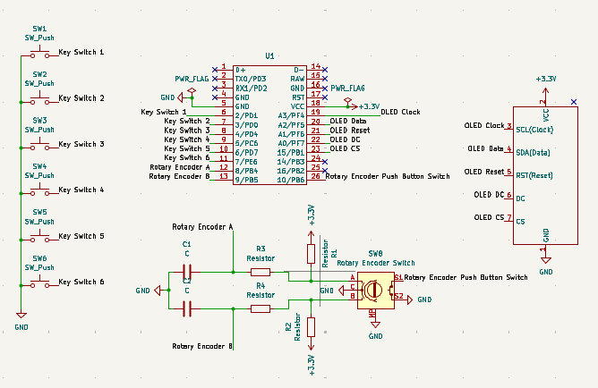
This schematic went through multiple, multiple changes. Like when I had to add power symbols, make a denouncer circuit, custom design the OLED symbol like 2 times, and change the GPIO pins for my OLED. I liked this portion a lot actually.
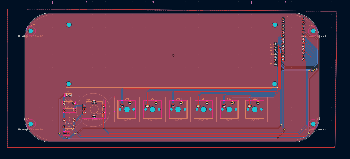
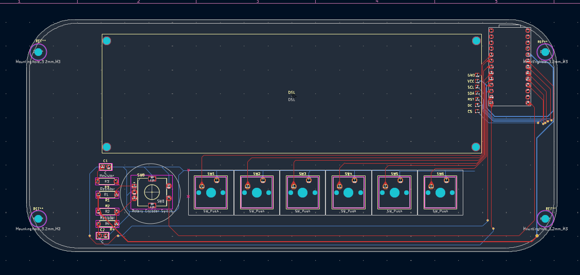
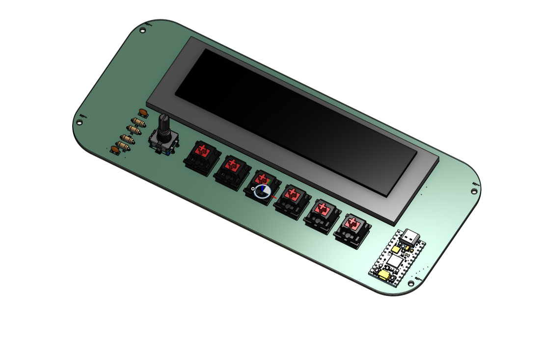
I added a lot of stuff bc the Internet said so :). So hopefully that was not a mistake. I was also just informed no 90 or acute angles so maybe not so final pcb :(.
This is relatively easy to use assuming it is all put together and well. All you need to do is drag firmware/software files into the KB2040 and let the host computer code run as a background process.
The computer process will be listening on a port. From there you can read the documentation available in code/keyboard/ on how to automate the OLED, switches, and encoder functions.
From there, it is just using the macropad as a macropad.
Since I have not had the pleasure of constructing this, I can't tell you for sure but below is how to build it if everything goes as planned.
Congrats! You have know constructed MORPH.00. Hopefully it should work.
Check bom.csv!
| Qty | Value | Footprint | References |
|---|---|---|---|
| 6 | SW_Push | Button_Switch_Keyboard:SW_Cherry_MX_1.00u_PCB | SW1, SW2, SW3, SW4, SW5, SW6 |
| 4 | Resistor | Resistor_THT:R_Axial_DIN0207_L6.3mm_D2.5mm_P7.62mm_Horizontal | R1, R2, R3, R4 |
| 2 | C | Capacitor_THT:C_Disc_D5.0mm_W2.5mm_P2.50mm | C1, C2 |
| 1 | Rotary Encoder Switch | Rotary_Encoder:RotaryEncoder_Alps_EC11E-Switch_Vertical_H20mm | SW8 |
| 1 | ~ | OLED:TZT_5.5_OLED_SSD1322 | DS1 |
| 1 | ~ | ScottoKeebs_MCU:Adafruit_KB2040 | U1 |
The 15 most common of 19 parts.
It measures 222.5 × 97.5 mm and has 2 copper layers, 1.6 mm thick.
19 parts. The full list of its parts is on this page, with links to each part's symbol and footprint where PCBKit's library has them.
From the nirvaankohli/MORPH.00 repository on GitHub, at the commit this page was made from: the board is hardware/kicad_files/morph00/morph00.kicad_pcb and its schematic hardware/kicad_files/morph00/morph00.kicad_sch. PCBKit opens the board in the browser, with nothing to install.
Its repository states no licence, so its author keeps all rights: ask nirvaankohli before reusing the design.

hackclub/OnBoard
💡 Join 1,000 teenagers and make your first PCB with a $100 grant!

polpo/picogus
Emulation of ISA sound cards and CD-ROM on Raspberry Pi Pico (GUS, SB/Adlib, MPU-401, Tandy, CMS, Panasonic CD-ROM) with USB mouse/joystick support


nkitanov/iaq_board
IAQ Board is a DIY (Do-It-Yourself) device for measuring internal air quality


Ardumower/ardumower
Develop an open source robotic lawn mower (HW+SW reference platform)

zmaker/arduino_cookbook
gli sketch del nuovo progetto Arduino Cookbook e dei video di YouTube