
4 layers56.4 × 56.4 mm

 ninemind/aeromax-throttle-module3
Unofficial, open-source DIY throttle module for the VIRPIL CDT-AEROMAX, with 3D-printable parts, KiCad PCB files, and assembly documentation.
Throttle Module is an open-source printed circuit board by ninemind, from the ninemind/aeromax-throttle-module repository on GitHub, published under the CERN-OHL-S-2.0 licence. It is a 2-layer board of 42 × 15 mm with 7 parts on 9 nets, routed with 37 tracks and 2 vias.
It is built around the MT6701CT-STD-R. Its parts include 2 crystals, 1 capacitor, 1 resistor and 1 IC.
An unofficial, community-built throttle module for the VIRPIL CDT-AEROMAX. This project began as a working replacement for the unavailable factory throttle module, but the interface can support much more than the original-style lever.
The design combines 3D-printed mechanical parts, a custom KiCad sensor PCB, and a magnetic position sensor. The module interface also provides a connection for an additional button, leaving room for custom levers, collectives, twin-throttle designs, and other original controls.

For ready-to-print files, tested print profiles, photos, and the illustrated assembly guide, see the MakerWorld project page. This repository is the canonical source for the editable CAD, KiCad design, and PCB manufacturing files.
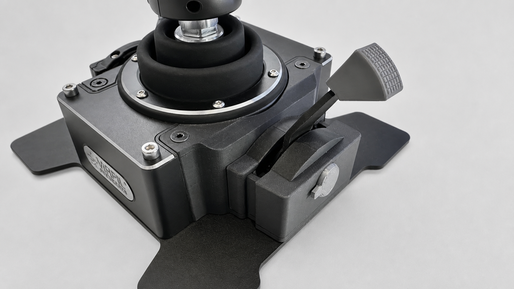
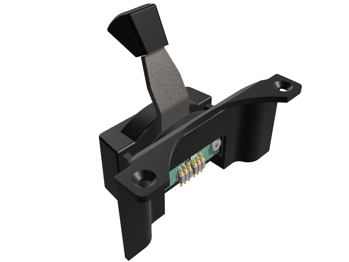
| Folder or file | Contents |
|---|---|
Aeromax_Throttle_Module.3mf | Printable mechanical model and print setup |
assembly.pdf | Illustrated mechanical assembly guide |
Aeromax_Throttle_Module.step | Neutral CAD exchange model for viewing and remixing |
images/ | Project renderings used in this README |
kikad/ | Editable KiCad schematic, PCB, and project files |
manufacturing/v1.0/ | Tested v1.0 Gerbers and JLCPCB assembly files |
Start with the illustrated assembly guide. It covers the required parts and the complete mechanical assembly sequence.
The PCB is a separate build step. The editable source is in kikad/; users who want JLCPCB assembly should use the files in manufacturing/v1.0/.
For the v1.0 PCB:
Aeromax_Throttle_Module_Gerbers_v1.0.zip to JLCPCB to order bare PCBs.Aeromax_Throttle_Module_JLCPCB_BOM_v1.0.csv and Aeromax_Throttle_Module_JLCPCB_CPL_v1.0.csv during the assembly order.Aeromax_Throttle_Module_KiCad_BOM_v1.0.csv and Aeromax_Throttle_Module_Position_Export_v1.0.csv are KiCad exports retained for reference. The JLCPCB-specific BOM and CPL are the files intended for JLCPCB assembly.
This design does not have to look like the original throttle module. Possible adaptations include:
If you make a variant, please share photos, source files, and notes that will help the next builder.
If this project was useful and you would like to support future designs:
This is an unofficial community project. It is not affiliated with, endorsed by, or supported by VIRPIL Controls. Verify fitment, wiring, and safe operation before installation. You build and use this project at your own risk.
Copyright (c) 2026 ninemind. This project is licensed under the CERN Open Hardware Licence Version 2 - Strongly Reciprocal (CERN-OHL-S-2.0). You may use, make, modify, and distribute the design and products based on it, provided that distributed modifications remain available under the same licence.
| Qty | Value | Footprint | References |
|---|---|---|---|
| 2 | 829-22-003-20-001101 | Virpil:MILL-MAX_829-22-003-20-001101 | X1, X2 |
| 1 | 100R | Resistor_SMD:R_0603_1608Metric | R1 |
| 1 | 1uF | Capacitor_SMD:C_0603_1608Metric | C1 |
| 1 | MT6701CT-STD-R | Package_SO:SO-8_3.9x4.9mm_P1.27mm | U1 |
The 5 most common of 7 parts.

gallicchio/AMOD-and-RFMOD
The tutorial's 2x12 adapter (/mudd/133electronics/icepi-zero-dac-adc/adapterboard/) with a 2 x 6 right-angle Pmod socket on a 15 mm extension of its right-hand end, so an Icepi Zero can drive AMOD-A's and RF-MOD's Pmod…

byrantech/laptop
anyon_e, a highly integrated, high end, open source laptop. Attempt the impossible.


AxxAxx/AxxSolder
STM32 Based soldering station for JBC cartridges, 9-24 VDC and USB-PD power


jamro/tiny-engineer
A small desktop robot that brings an AI coding assistant to life, physically acting out when it reads files, thinks, writes code, and finishes work.
It measures 42 × 15 mm and has 2 copper layers, 1.6 mm thick.
7 parts, built around the MT6701CT-STD-R. The full list of its parts is on this page, with links to each part's symbol and footprint where PCBKit's library has them.
From the ninemind/aeromax-throttle-module repository on GitHub, at the commit this page was made from: the board is kikad/Throttle Module.kicad_pcb and its schematic kikad/Throttle Module.kicad_sch. PCBKit opens the board in the browser, with nothing to install.
Its repository publishes it under the CERN-OHL-S-2.0 licence: you may reuse it on that licence's terms (keep the author's notice, and for a copyleft licence share your changes alike).