2 layers192.2 × 150.5 mm

 NileDex/NIDX-PM-26
The module provides active reverse polarity protection, programmable current-limiting switches with hardware fault flags, and high-precision 20-bit digital power monitoring (voltage, current, power, and energy…
Mcu protection is an open-source printed circuit board by NileDex, from the NileDex/NIDX-PM-26 repository on GitHub, published under the MIT licence. It is a 2-layer board of 45 × 24 mm with 25 parts on 18 nets, routed with 297 tracks and 26 vias.
It is built around the TPS2553DBVR-1 and AO3401A. Its parts include 8 capacitors, 6 resistors, 4 ICs, 3 connectors and 2 transistors.



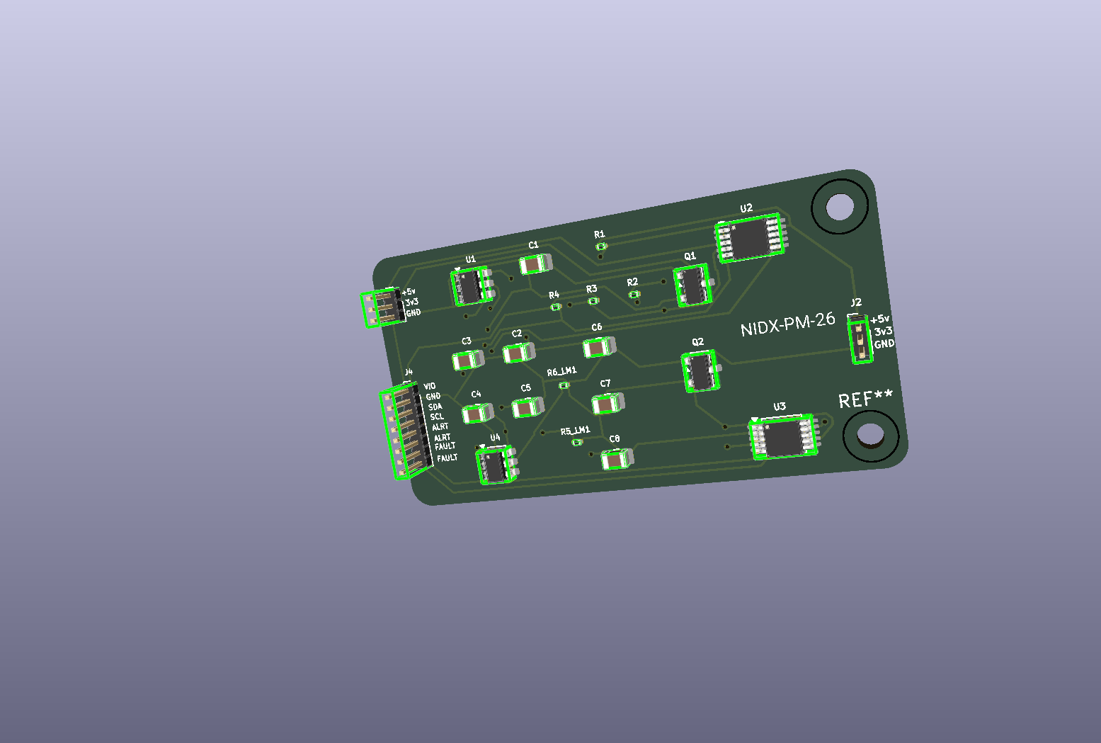
NIDX-PM-26 is a dual-channel power distribution, circuit protection, and telemetry module designed by NileDex for microcontrollers (MCUs), development boards (ESP32, STM32, Arduino, Raspberry Pi), and sensitive embedded systems.
The module provides active reverse polarity protection, programmable current-limiting switches with hardware fault flags, and high-precision 20-bit digital power monitoring (voltage, current, power, and energy accumulation) over a shared I2C bus.
AO3401A) prevent reverse-voltage damage with negligible voltage drop compared to traditional Schottky diodes.TPS2553DBVR power switches with programmable current limit threshold, fast short-circuit response, and thermal shutdown with auto-recovery.
FAULT (TPS2553) and programmable ALERT (INA228) outputs broken out for direct microcontroller interrupt handling.VDD_I2C pin, allowing seamless operation with 1.8V, 3.3V, or 5V microcontroller logic. CHANNEL 1
J1 Pin 1 ──► [Q1: AO3401A] ──► [U1: TPS2553] ──► [R1: 0.1Ω Shunt] ──► J2 Pin 1
(VIN1) (Reverse Protect) (Current Limit) │ (VOUT1)
│ ▼
│ [U2: INA228]
▼ (20-bit I2C: 0x40)
FAULT1 ──► J4 Pin 7 │
ALERT1 ──► J4 Pin 5
CHANNEL 2
J1 Pin 2 ──► [Q2: AO3401A] ──► [U4: TPS2553] ──► [R2: 0.1Ω Shunt] ──► J2 Pin 2
(VIN2) (Reverse Protect) (Current Limit) │ (VOUT2)
│ ▼
│ [U3: INA228]
▼ (20-bit I2C: 0x44)
FAULT2 ──► J4 Pin 8 │
ALERT2 ──► J4 Pin 6
CONTROL & I2C INTERFACE (J4)
J4 Pin 1 ──► VDD_I2C (Pull-up Reference: 1.8V - 5V)
J4 Pin 2 ──► GND
J4 Pin 3 ──► SDA (Shared I2C Data bus, 4.7kΩ pull-up R3)
J4 Pin 4 ──► SCL (Shared I2C Clock bus, 4.7kΩ pull-up R4)Q1, Q2)AO3401A (-30V, -4.0A, SOT-23 P-Channel MOSFET).U1, U4)TPS2553DBVR (SOT-23-6).EN) tied to IN for automatic power pass-through.R5_LM1 and R6_LM1 ($47\text{ k}\Omega$):
$$I_{OS(typ)} \approx \frac{24212}{(R_{ILIM})^{0.985}} \approx \frac{24212}{(47000)^{0.985}} \approx 595\text{ mA}$$
(Nominal continuous working current: $\sim 500\text{ mA}$).FAULT pin signals over-current or thermal shutdown events to the host MCU via J4.U2, U3)Part: Texas Instruments INA228 (TSSOP-10).
Resolution: 20-bit Delta-Sigma ADC with $1\text{ }\mu\text{V}$ shunt voltage LSB and $195.3125\text{ }\mu\text{V}$ bus voltage LSB.
Current Sense Resistors: R1, R2 = $0.1\text{ }\Omega$ ($100\text{ m}\Omega$, 0805 SMD package).
I2C Addressing:
| Channel | IC Designator | A1 Pin | A0 Pin | 7-bit I2C Address (Hex) | 7-bit I2C Address (Binary) |
|---|---|---|---|---|---|
| Ch 1 | U2 | GND | GND | 0x40 | 1000000b |
| Ch 2 | U3 | VS (Rail) | GND | 0x44 | 1000100b |
Alert Pins: Open-drain output asserted when programmed power, current, or voltage limits are exceeded.
| Pin # | Silkscreen | Signal | Type | Description |
|---|---|---|---|---|
| 1 | +5v | VIN1 | Power Input | Channel 1 Input Voltage (+2.5V to +6.5V) |
| 2 | 3v3 | VIN2 | Power Input | Channel 2 Input Voltage (+2.5V to +6.5V) |
| 3 | GND | GND | Ground | Common Power Ground |
| Pin # | Silkscreen | Signal | Type | Description |
|---|---|---|---|---|
| 1 | +5v | VOUT1 | Power Output | Channel 1 Protected & Monitored Power Output |
| 2 | 3v3 | VOUT2 | Power Output | Channel 2 Protected & Monitored Power Output |
| 3 | GND | GND | Ground | Common Power Ground |
| Pin # | Silkscreen | Signal | Type | Description |
|---|---|---|---|---|
| 1 | VIO | VDD_I2C | Power Input | I2C pull-up reference voltage (1.8V, 3.3V, or 5V MCU logic) |
| 2 | GND | GND | Ground | System Ground reference for digital signals |
| 3 | SDA | SDA | I/O | I2C Data line (pulled up via R3 $4.7\text{ k}\Omega$ to VIO) |
| 4 | SCL | SCL | Input | I2C Clock line (pulled up via R4 $4.7\text{ k}\Omega$ to VIO) |
| 5 | ALRT | ALERT1 | Output (OD) | Channel 1 INA228 programmable threshold alert |
| 6 | ALRT | ALERT2 | Output (OD) | Channel 2 INA228 programmable threshold alert |
| 7 | FAULT | FAULT1 | Output (OD) | Channel 1 TPS2553 fault flag (Active Low) |
| 8 | FAULT | FAULT2 | Output (OD) | Channel 2 TPS2553 fault flag (Active Low) |
| Parameter | Min | Typical | Max | Unit | Notes |
|---|---|---|---|---|---|
| Input Voltage ($V_{IN}$) | 2.5 | 3.3 / 5.0 | 6.5 | V | Limited by TPS2553 supply range |
| Current Limit Threshold ($I_{LIMIT}$) | 450 | 500 | 600 | mA | Configured by $47\text{ k}\Omega$ $R_{ILIM}$ resistors |
| Current Sense Resistance ($R_{SHUNT}$) | - | 0.1 | - | $\Omega$ | Tolerance 1%, 0805 package |
| Reverse Polarity Voltage Blocking | - | - | -30 | V | $V_{DS(max)}$ of AO3401A |
| I2C Bus Speed | 10 | 400 | 1000 | kHz | Standard, Fast, and Fast-Mode+ supported |
Digital Logic Voltage (VDD_I2C) | 1.8 | 3.3 | 5.5 | V | Feeds pull-ups R3 and R4 |
| Operating Ambient Temperature | -40 | +25 | +85 | °C | Industrial rated components |
| Designator | Value / Part Number | Description | Footprint / Package |
|---|---|---|---|
| U1, U4 | TPS2553DBVR | Precision Adj. Current-Limited Switch | SOT-23-6 |
| U2, U3 | INA228 | 20-bit Current/Power/Energy Monitor | TSSOP-10 (3x3mm, 0.5mm pitch) |
| Q1, Q2 | AO3401A | P-Channel MOSFET (-30V, -4.0A) | SOT-23-3 |
| R1, R2 | 0.1 ($100\text{ m}\Omega$) | Current Shunt Resistor, 1% | SMD 0805 |
| R3, R4 | 4.7k | I2C Bus Pull-Up Resistors | SMD 0805 |
| R5_LM1, R6_LM1 | 47k | Current Limit Set Resistors (TPS2553) | SMD 0805 |
| C1, C2, C3, C4 | 100n ($0.1\text{ }\mu\text{F}$) | Ceramic Decoupling Capacitors, 50V | SMD 0805 |
| C5, C6, C7, C8 | 10u ($10\text{ }\mu\text{F}$) | Ceramic Bulk Filter Capacitors, 16V/25V | SMD 0805 |
| J1, J2 | Conn_01x03 | 3-pin Power Input/Output Header | 1x03 Pin Header (1.00mm pitch) |
| J4 | Conn_01x08 | 8-pin Diagnostics & Telemetry Header | 1x08 Pin Header (1.00mm pitch) |
#include <Wire.h>

// I2C Addresses
#define INA228_CH1_ADDR 0x40
#define INA228_CH2_ADDR 0x44

// Pin Definitions on Host MCU
#define PIN_FAULT1 4
#define PIN_FAULT2 5
#define PIN_ALERT1 6
#define PIN_ALERT2 7

void setup() {
  Serial.begin(115200);
  Wire.begin();

  pinMode(PIN_FAULT1, INPUT_PULLUP);
  pinMode(PIN_FAULT2, INPUT_PULLUP);
  pinMode(PIN_ALERT1, INPUT_PULLUP);
  pinMode(PIN_ALERT2, INPUT_PULLUP);

  Serial.println("NIDX-PM-26 Initialized.");
}
mcu-protection/
├── .gitignore                     # Git ignore rules (schematics, netlists & temporary files ignored)
├── LICENSE                        # MIT License
├── README.md                      # Hardware documentation and wiring guide
├── mcu-protection.kicad_pro       # KiCad 10 project file
├── mcu-protection.kicad_pcb       # KiCad PCB layout
├── mcu-protection.png             # PCB 3D preview render
└── ERC.rpt # Electrical Rules Check reportThis project is licensed under the MIT License. Copyright (c) 2026 NileDex (NIDX-PM-26 Contributors).
| Qty | Value | Footprint | References |
|---|---|---|---|
| 4 | 100n | Capacitor_SMD:C_0805_2012Metric | C1, C2, C3, C4 |
| 4 | 10u | Capacitor_SMD:C_0805_2012Metric | C5, C6, C7, C8 |
| 2 | 0.1 | Resistor_SMD:R_0201_0603Metric | R1, R2 |
| 2 | 4.7k | Resistor_SMD:R_0201_0603Metric | R3, R4 |
| 2 | 47K | Resistor_SMD:R_0201_0603Metric | R5_LM1, R6_LM1 |
| 2 | AO3401A | Package_TO_SOT_SMD:SOT-23 | Q1, Q2 |
| 2 | Conn_01x03 | Connector_PinHeader_1.00mm:PinHeader_1x03_P1.00mm_Vertical | J1, J2 |
| 2 | INA228 | Package_SO:TSSOP-10_3x3mm_P0.5mm | U2, U3 |
| 2 | TPS2553DBVR | Package_TO_SOT_SMD:SOT-23-6 | U1, U4 |
| 1 | Conn_01x08 | Connector_PinHeader_1.00mm:PinHeader_1x08_P1.00mm_Vertical | J4 |
The 23 most common of 25 parts.


barkinvar/sugerCANe
A compact interface for three NPN, PNP or logic sensors on an FRC robot. Each port has a removable 5 V / 12 V power jumper; input type is configured in software.

bornier-dev/bornier
Open source EtherCAT slaves for machine tools running LinuxCNC: hardware, firmware and tooling.

jasonlaguidice/TKL-Split-Keyboard
Board edge fillet plugin used: https://github.com/tywtyw2002/FilletEdge


open-pasture/opencollar
OpenCollar: a virtual-fence collar you can buy assembled or build from published parts.

printsmith/keyboards
Custom keyboard featuring a modified Southpaw 1800 layout with 2 nav clusters, LCD display and rotary encoders.
It measures 45 × 24 mm and has 2 copper layers, 1.6 mm thick.
25 parts, built around the TPS2553DBVR-1 and AO3401A. The full list of its parts is on this page, with links to each part's symbol and footprint where PCBKit's library has them.
From the NileDex/NIDX-PM-26 repository on GitHub, at the commit this page was made from: the board is mcu-protection.kicad_pcb. PCBKit opens the board in the browser, with nothing to install.
Its repository publishes it under the MIT licence: you may reuse it on that licence's terms (keep the author's notice, and for a copyleft licence share your changes alike).