4 layers55.3 × 70.2 mm
FCC KiCAD
nikphillydev/NP1_DRONE
Building a quadcopter from scratch. Hardware and software. Developed using STM32 microcontroller and FreeRTOS.
116 parts3MIT

 nikphillydev/NP1_DRONE3
Building a quadcopter from scratch. Hardware and software. Developed using STM32 microcontroller and FreeRTOS.
ESC v2 is an open-source printed circuit board by nikphillydev, from the nikphillydev/NP1_DRONE repository on GitHub, published under the MIT licence. It is a 4-layer board of 102.5 × 45 mm with 150 parts on 89 nets, routed with 614 tracks and 316 vias.
It is built around the STM32G474CET6, SN65HVD232DR-JSM and IRS21867STRPBF, with the TLV75533PDBVR-MS, TPH1R306P1,L1Q and S2B-PH-K-S-GW among its other parts. Its parts include 49 capacitors, 41 resistors, 25 diodes, 9 ICs and 7 connectors. It belongs with the robots and motor control boards and the STM32 boards of this library.


I am attempting to build a quadcopter from scratch, both the PCB hardware (using KiCAD) and software (C/C++ on STM32).
I am a computer software engineering student at the University of Alberta. I started this project in early 2024 to push myself with embedded systems. Since its inception, I have learned a ton about PCB design and FreeRTOS firmware on STM32 microcontrollers.
Everything I make in this project is from scratch. The STM32-based circuit boards are designed with KiCAD and ordered from JLCPCB with assembly. I am using FreeRTOS for the software because of its scalability in complex embedded projects. I have written all the device drivers from scratch, and wholly designed the multi-threaded architecture for each of the drone's sub-systems.
Each sub-system presents its own set of challenges. As an overview, there are 3 sub-systems of the NP1 Drone:
                     (Over-The-Air Messaging)                               (CANBUS)
[RC CONTROLLER] <----------------------------> [Flight Controller] <---------------> [Electronic Speed Controller] x4The Flight Controller (FCC) is a custom PCB design whose software runs the control system for the drone. In order to achieve this, it must 1) receive pilot input from the RC Controller, and 2) estimate its attitude and heading (roll, pitch, yaw). These inputs enter the onboard PID controller in order to calculate the necessary motor commands to send to the Electronic Speed Controllers (ESCs).
The FCC is equipped with a multitude of sensors, namely an IMU, magnetometer, barometer, optical flow sensor, and range finder. It performs sensor fusion through the use of an Extended Kalman Filter (EKF) and a few other custom algorithms. When it receives Over-The-Air (OTA) messages from the RC Controller, it monitors for a HEARTBEAT signal to detect LOSS-OF-LINK and perform flight termination. The control system interprets pilot input and sets the target roll, pitch, and yaw accordingly depending on flight mode (various flight modes still WIP).
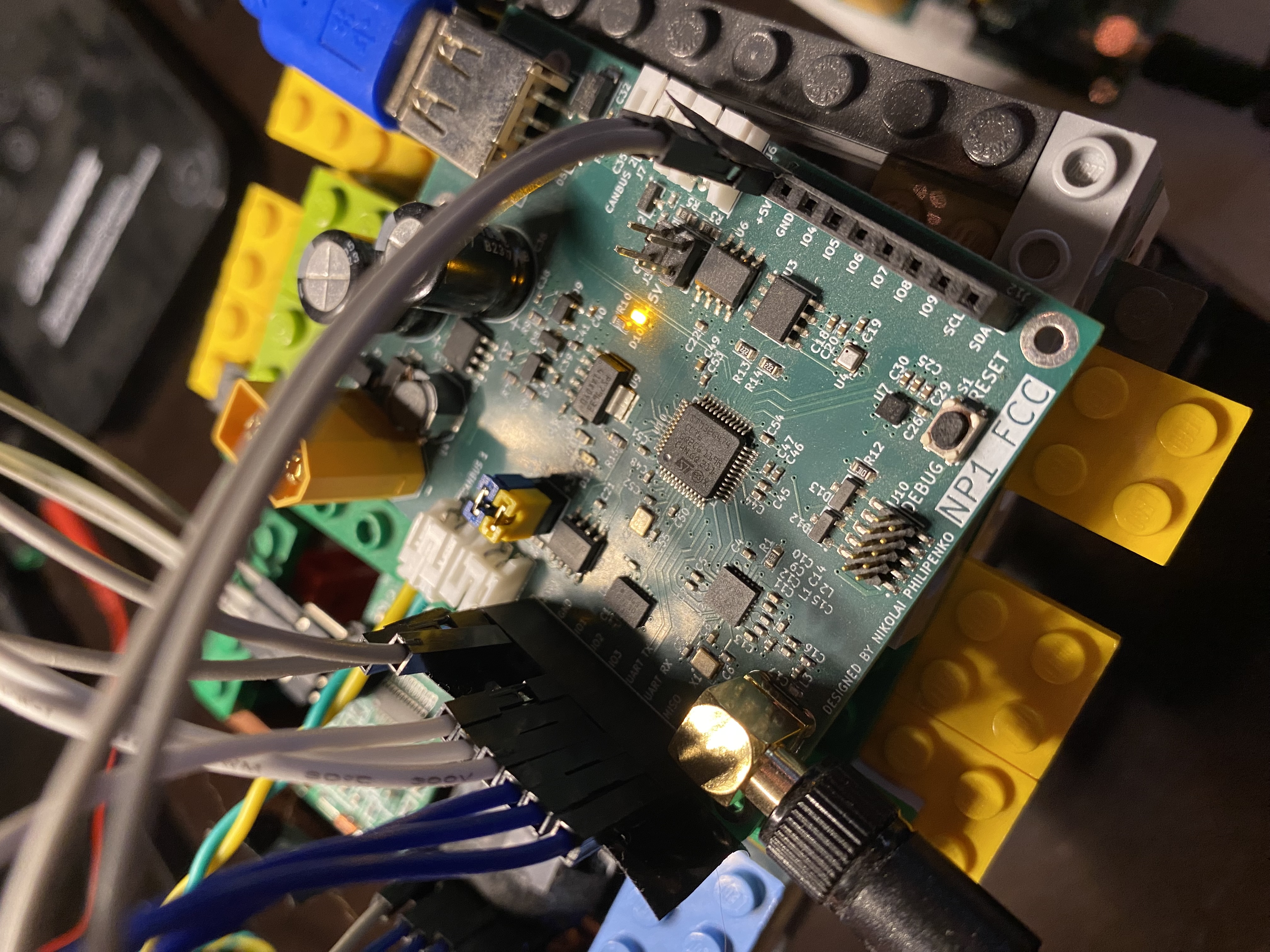
Figure 1: The Flight Controller (FCC) sitting on a Lego frame. The USB powers the board and enables logging to my laptop; jumper wires connect the external range finder and optical flow sensor; the green and yellow twisted pair connect to the ESCs using CANBUS.
The RC Controller is simple: receive pilot input from various joysticks and buttons and send those values Over-The-Air (OTA) to the FCC. A custom OTA messaging protocol (modelled after MAVLINK) has been developed to facilitate this communication. The physical inputs of the RC Controller are fairly WIP right now. Currently, its a breadboard with push-buttons and a potentiometer, (hopefully) soon it will be a PS4 controller.
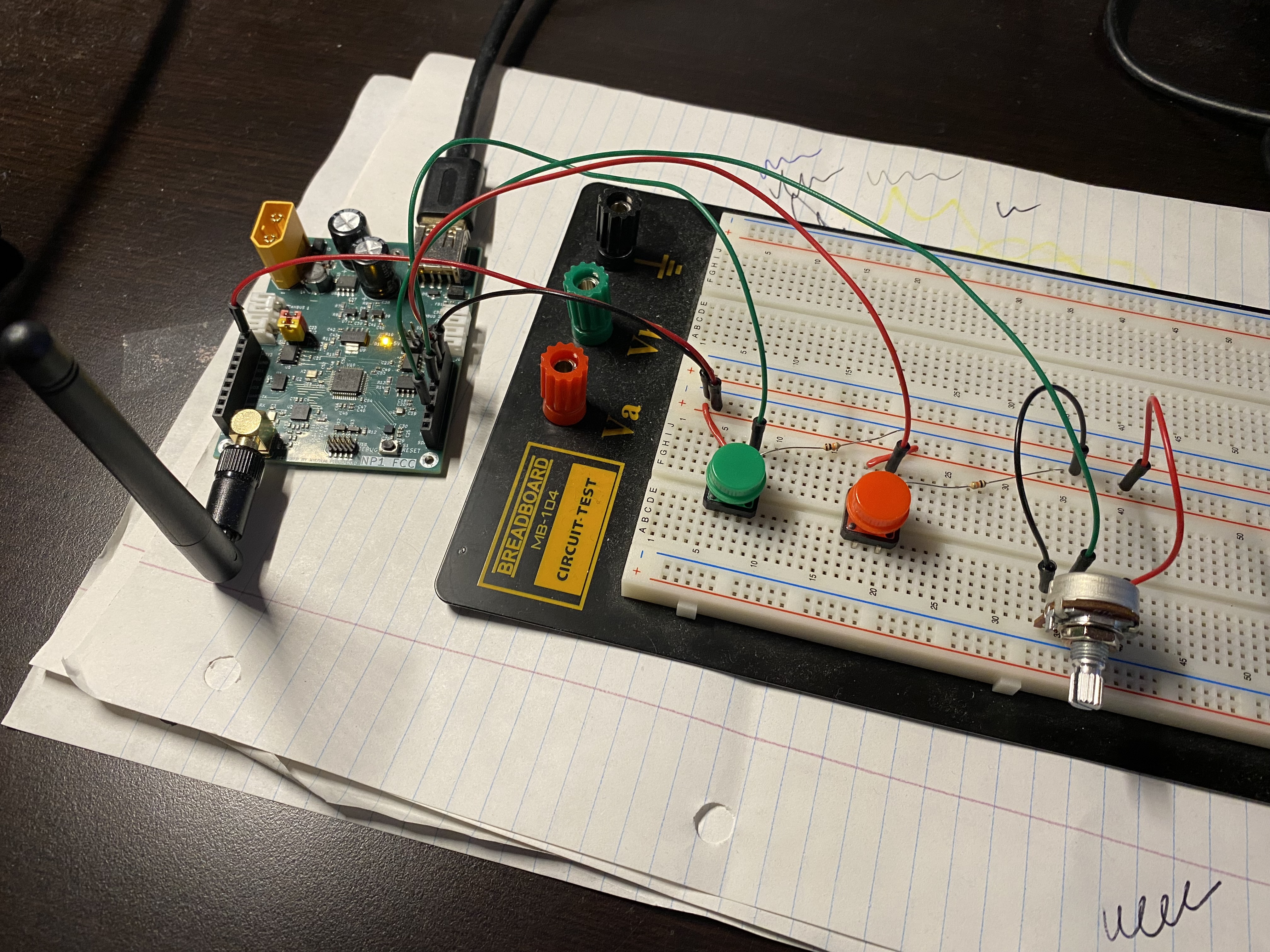
Figure 2: The RC Controller, in its current state. Spare hardware is used to capture pilot input.
The Electronic Speed Controller (ESC) requires a strong understanding of Brushless DC (BLDC) motor control. The custom PCB design and software are designed around the (sensorless) 6-Step Trapezoidal control method, where a Back Electromotive Force (BEMF) measurement from the floating motor phase is measured in order to know when to switch the commutation to the next step. In order to perform proper closed-loop control in this method, the motor must be spinning fast enough to generate a sufficient BEMF. I designed the ESC to operate in a software defined state-machine. Here are the states:
The ESC receives ARM, DISARM, and THROTTLE CANBUS messages from the FCC to transition between its internal states and increase / decrease motor RPM.
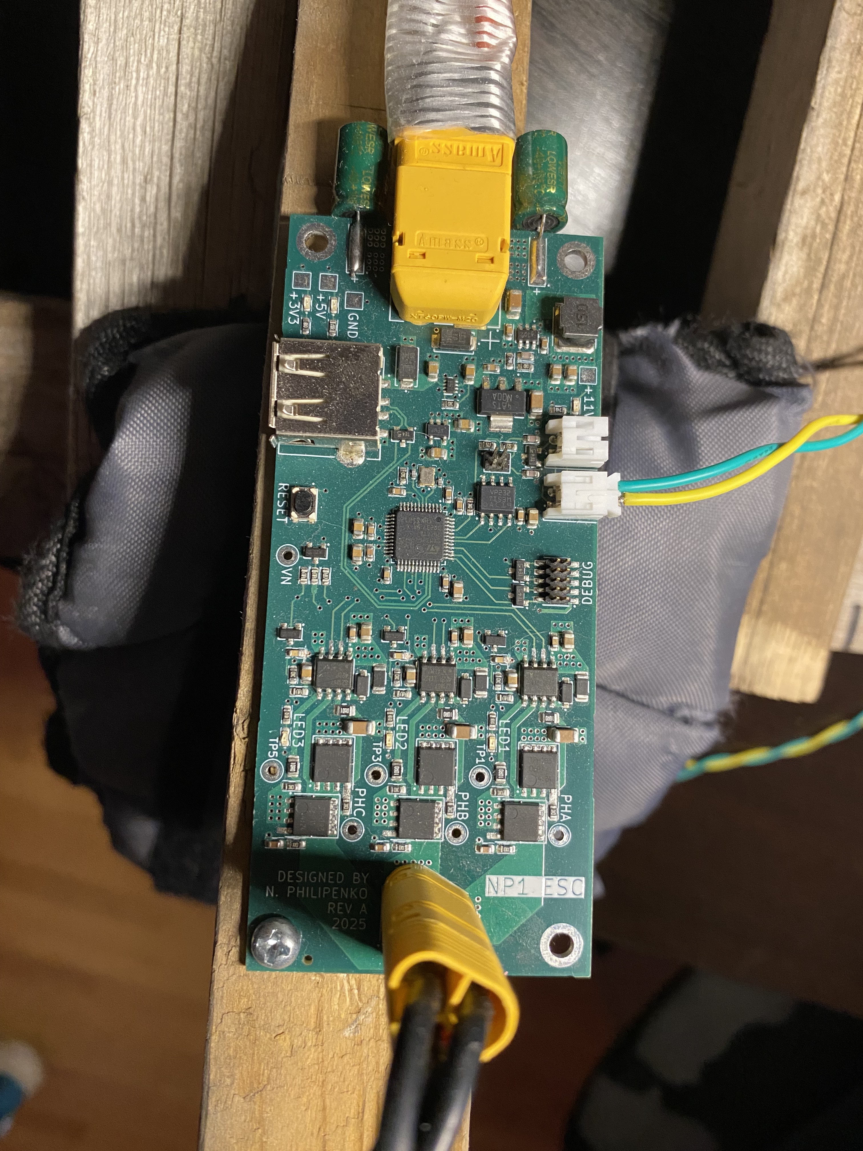 Figure 2: The Electronic Speed Controller (ESC), connected to the FCC via CANBUS. |
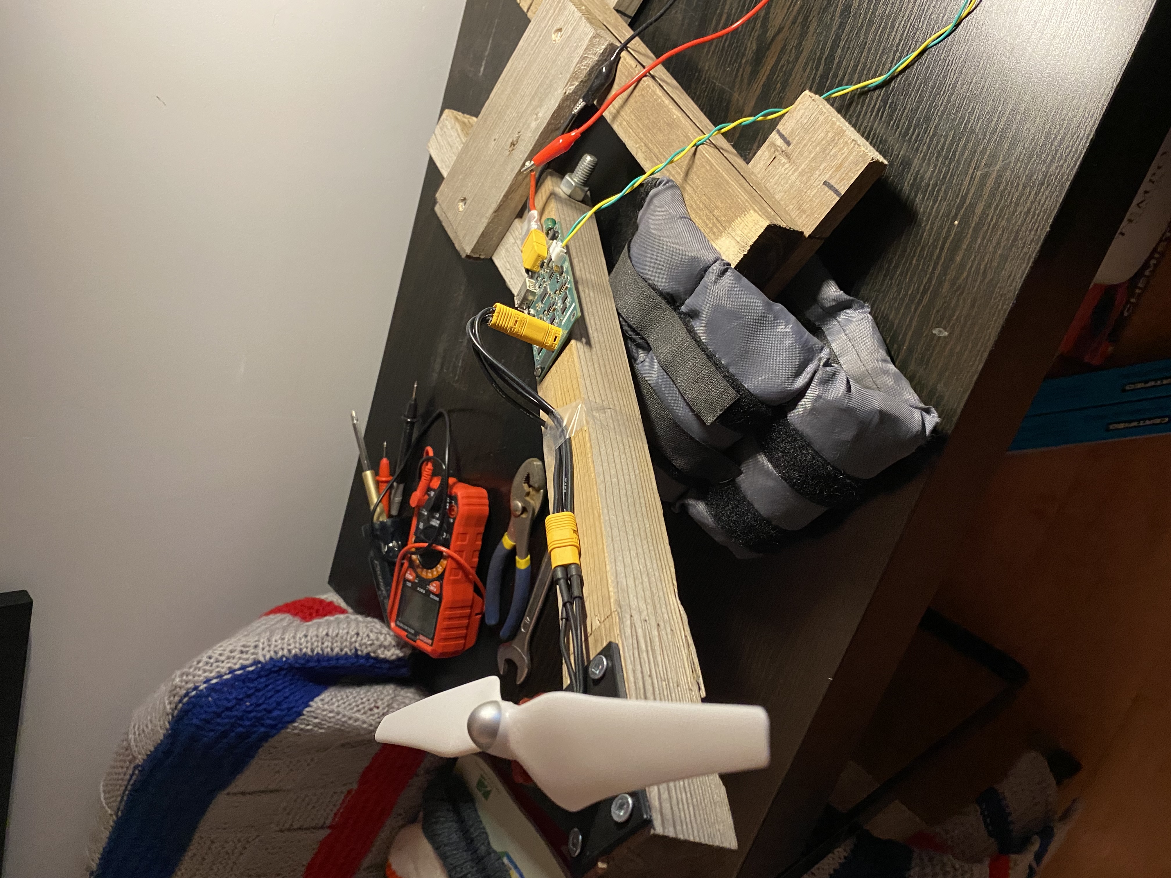 Figure 3: The motor test stand; an ESC and BLDC motor mounted onto a wooden lever. |
This demo showcases the RC Controller sending my input Over-The-Air (OTA) to the FCC. The FCC receives these commands and uses its estimated state to calculate motor commands in its control system. The resulting commands are sent via CANBUS to the ESC on the motor test stand, controlling the BLDC motor.
https://github.com/user-attachments/assets/3e73fd2b-c005-44b4-9096-01581734d467
For more detailed design, please see the hardware and software folders.
Here is the hardware overview.
Here is the software overview.
When I started the project in 2024, zero AI was used. Now, from 2026 onward, AI is obviously much better. However, this is a PASSION PROJECT. The goal of this project is to LEARN. I will not be able to effectively achieve that goal if I use AI. The intelligence you gain from AI is artificial. Therefore, I write all the code MYSELF. If there are bugs or I want some review / feedback of my work, I will use AI to do so. In this way, AI is the reviewer and I formulate my own thoughts first.
| Qty | Value | Footprint | References |
|---|---|---|---|
| 13 | 100nF | Capacitors:CAP_0603_1608Metric | C2, C9, C12, C18, C27, C28, C31, C39, C42, C44, C45, C47, C49 |
| 12 | 10k | Resistors:RES_0603_1608Metric | R4, R5, R9, R14, R15, R17, R22, R23, R25, R27, R34, R35 |
| 9 | 1uF | Capacitors:CAP_0805_2012Metric | C3, C13, C19, C29, C30, C33, C36, C38, C40 |
| 7 | TestPoint | TestPoint:TestPoint_THTPad_D2.5mm_Drill1.2mm | TP1, TP2, TP3, TP4, TP5, TP6, TP11 |
| 6 | 10R | Resistors:RES_0805_2012Metric | R2, R3, R12, R13, R20, R21 |
| 6 | 68k | Resistors:RES_0603_1608Metric | R8, R16, R24, R37, R38, R39 |
| 6 | LED | Diodes:LED_0603_1608Metric | D17, D18, D19, D23, D24, D25 |
| 6 | TPH1R306P1,L1Q | Diodes:PQFN-8-EP_6x5mm_P1.27mm_Generic | D3, D4, D7, D8, D11, D12 |
| 5 | 10nF | Capacitors:CAP_0603_1608Metric | C10, C16, C22, C37, C41 |
| 5 | 10uF | Capacitors:CAP_1206_3216Metric | C6, C14, C20, C23, C26 |
| 5 | 4.7uF | Capacitors:CAP_0805_2012Metric | C1, C8, C11, C17, C43 |
| 4 | 1k | Resistors:RES_0603_1608Metric | R33, R36, R40, R41 |
| 4 | BZX84C3V3-7-F | Diodes:DiodesINC_SOT23-3 | D5, D9, D13, D22 |
| 4 | D1213A-02SOL-7 | Diodes:DiodesINC_SOT23-3 | D2, D16, D20, D21 |
| 4 | MountingHole | MountingHole:MountingHole_3.2mm_M3_ISO7380_Pad | H1, H2, H3, H4 |
| 4 | TestPoint | TestPoint:TestPoint_Pad_2.0x2.0mm | TP7, TP8, TP9, TP10 |
| 3 | 10R | Resistors:RES_0603_1608Metric | R10, R18, R26 |
| 3 | 1nF | Capacitors:CAP_0603_1608Metric | C7, C15, C21 |
| 3 | 2.2R | Resistors:RES_1206_3216Metric | R1, R11, R19 |
| 3 | IRS21867STRPBF | ICs:SOIC-8 | U1, U3, U4 |
| 3 | MBR0580S1-7 | Diodes:DiodesINC_SOD123 | D1, D6, D10 |
| 2 | 11pF | Capacitors:CAP_0402_1005Metric | C46, C48 |
| 2 | 120R | Resistors:RES_0603_1608Metric | R6, R7 |
| 2 | 22uF | Capacitors:CAP_0805_2012Metric | C34, C35 |
| 2 | 330uF | Capacitors:CAP_ALUM_HORIZONTAL | C24, C25 |
| 2 | 47pF | Capacitors:CAP_0603_1608Metric | C4, C5 |
| 2 | 5.76k | Resistors:RES_0603_1608Metric | R29, R31 |
| 2 | S2B-PH-K-S | Connectors:CONN_JST_S2B-PH-K-S | J1, J2 |
| 2 | SMAJ28CA | Diodes:Littelfuse_SMA | D14, D15 |
| 1 | 100k | Resistors:RES_0603_1608Metric | R28 |
| 1 | 100pF | Capacitors:CAP_0603_1608Metric | C32 |
| 1 | 15uH | Inductors:L_6045S | L1 |
| 1 | 2x2-1.27MM | Connectors:CONN_MALE_TH_1.27MM_2x2 | J3 |
| 1 | 2x5-1.27MM | Connectors:CONN_MALE_SMT_1.27MM_2x5 | J6 |
| 1 | 3k | Resistors:RES_0603_1608Metric | R32 |
| 1 | 4.7k | Resistors:RES_0603_1608Metric | R30 |
| 1 | LM66200DRLR | ICs:TI_SOT-5X3 | U7 |
| 1 | LM7805MPX/NOPB | ICs:TI_SOT223-4 | U5 |
| 1 | MT60 | Connectors:CONN_MALE_TH_MT60 | J7 |
| 1 | NTC 10k | Resistors:RES_0603_1608Metric | TH1 |
| 1 | NX2520SA-16MHz | CrystalsAndOscillators:NDK_NX2520SA | X1 |
| 1 | SKRPARE010 | Switches:TACT_SKRP | S1 |
| 1 | SN65HVD232DR | ICs:SOIC-8 | U2 |
| 1 | STM32G474CET6 | ICs:STM_LQFP48 | U9 |
| 1 | TLV75533PDBVR | ICs:TI_SOT23-5 | U8 |
| 1 | TPS54302DDCR | ICs:TI_SOT23-6 | U6 |
| 1 | USB TYPE-A | Connectors:USB2.0_4P_AMPHENOL_87583-2010BLF | J5 |
| 1 | XT60PW-M | Connectors:CONN_MALE_TH_XT60PW | J4 |
nikphillydev/NP1_DRONE
Building a quadcopter from scratch. Hardware and software. Developed using STM32 microcontroller and FreeRTOS.

vagarthgaurav/ESP32-C3-breakout-board
A simple breakout board for the ESP32-C3 Microcontroller. It uses a chip antenna for wifi and bluetooth. It has an RGB LED on pin 10.

antmicro/gpu-cluster-backplane
This project contains open hardware design files for a PCB supporting power distribution in a cluster composed of GPUs. This board has been derived from an open source d1600e-psu-breakout created by Antmicro.

jbush001/HeadphoneGuitarPracticeAmp
Portable headphone amplifier/effects processor for electric guitar practice.


aliahumanoid/alia-humanoid-core
Humanoid research project (Phase 0): firmware, host software, STL files and electronics for tendon-driven joints inside real human proportions. GPLv3 software, CC BY-NC-ND hardware files.


matthewSorensen/pewpew-laserboard
LaserBoard is an open source controller for fiber laser marking systems, based around a Teensy 4.1 MCU board. LaserBoard provides a USB interface compatible with most low-cost fiber laser sources and XY-100-speaking…
It measures 102.5 × 45 mm and has 4 copper layers, 1.61 mm thick.
150 parts, built around the STM32G474CET6, SN65HVD232DR-JSM, IRS21867STRPBF and TLV75533PDBVR-MS. The full list of its parts is on this page, with links to each part's symbol and footprint where PCBKit's library has them.
From the nikphillydev/NP1_DRONE repository on GitHub, at the commit this page was made from: the board is hardware/Electronic Speed Controller/ESC_v2/ESC_v2.kicad_pcb and its schematic hardware/Electronic Speed Controller/ESC_v1/ESC_v1.kicad_sch. PCBKit opens the board in the browser, with nothing to install.
Its repository publishes it under the MIT licence: you may reuse it on that licence's terms (keep the author's notice, and for a copyleft licence share your changes alike).