
4 layers65 × 30 mm
Soleil
protolux-electronics/soleil_hardware
Hardware design files for Soleil, an open source power management and sleep control board for Raspberry Pi
81 parts22CERN-OHL-P-2.0

 nikolai2111/RaspberryPi-UART_Ethernet_Adapter
This adapter board enables the creation of a stand-alone, network-compatible device using any Raspberry Pi compatible UART daughterboard.
RaspberryPi UART Ethernet Adapter is an open-source printed circuit board by nikolai2111, from the nikolai2111/RaspberryPi-UART_Ethernet_Adapter repository on GitHub, published under the CERN-OHL-P-2.0 licence. It is a 2-layer board of 67 × 40 mm with 28 parts on 30 nets, routed with 126 tracks and 29 vias.
It is built around the TLV1117-33DCY and USB4125-GF-A. Its parts include 7 connectors, 4 resistors, 2 capacitors, 2 diodes and 1 IC. It belongs with the interfaces and adapters boards of this library.
[blocked]





This adapter board enables the creation of a stand-alone, network-compatible device using any Raspberry Pi compatible UART daughterboard.
Explore the docs »
View Demo
·
Report Bug
·
Request Feature
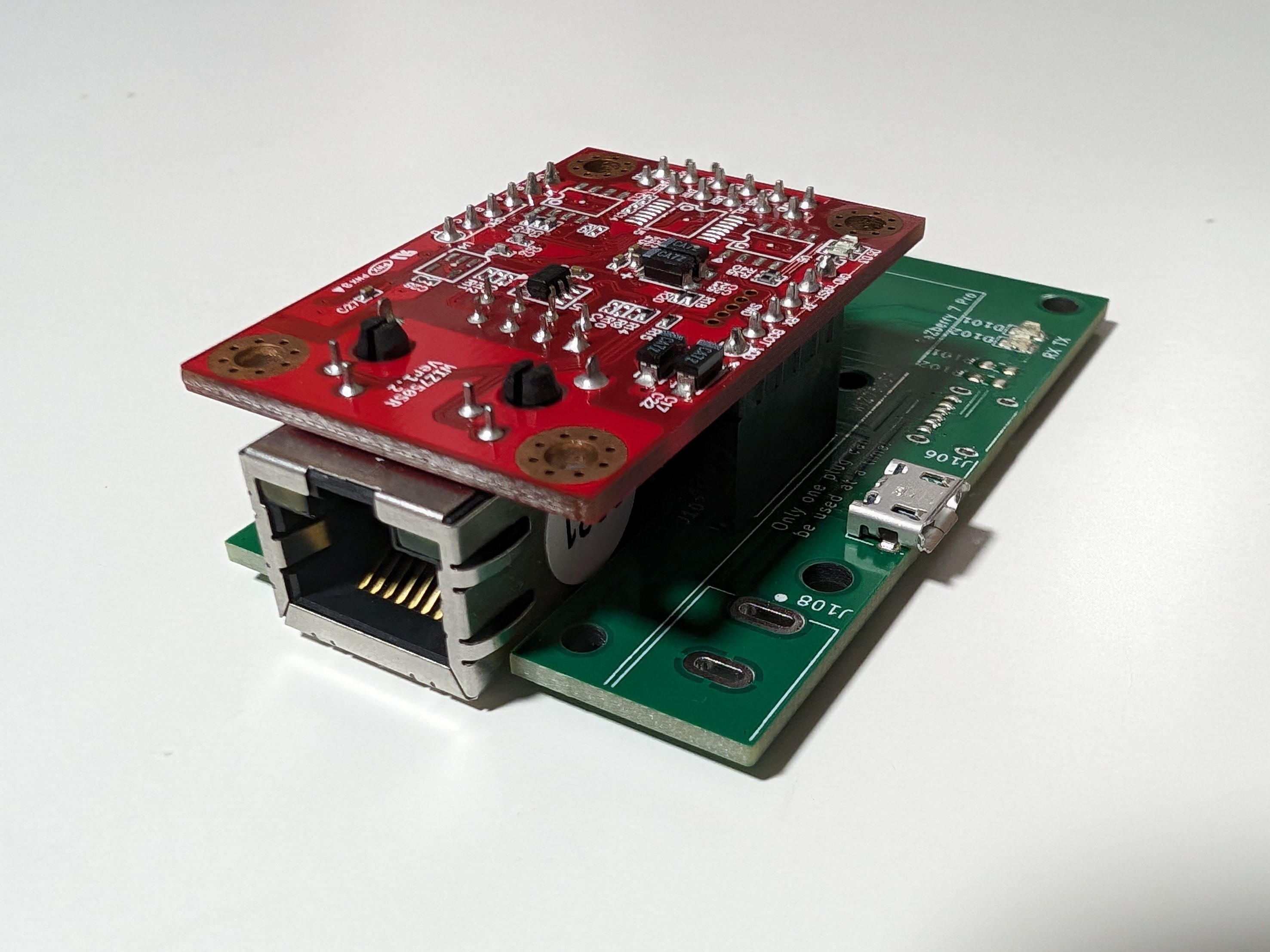
This adapter board enables the creation of a stand-alone, network-compatible device using any Raspberry Pi compatible UART daughterboard. The adapter board is used to connect the daughterboard of the Raspberry Pi and WIZ750SR-TTL. The adapter board connects the daughterboard of the Raspberry Pi to the WIZ750SR-TTL. It also provides a 5V and 3.3V power supply where necessary.
The adapter board was initially designed to connect the RaZberry 7 Pro to Home Assistant via TCP, without using a Raspberry Pi as a server. It can also be used with any Raspberry Pi daughterboard that only needs the TTL-UART interface. However, the following README refers to the use of the RaZberry 7 Pro with Home Assistant. It is possible to map three GPIOs to the header, although this has not been tested yet.
The board or as a kit (incl. WIZ750SR) can be purchased here. The board is available with three power supply options (power supply not inlcuded):

Device SearchBasic Settings as shown in the picture below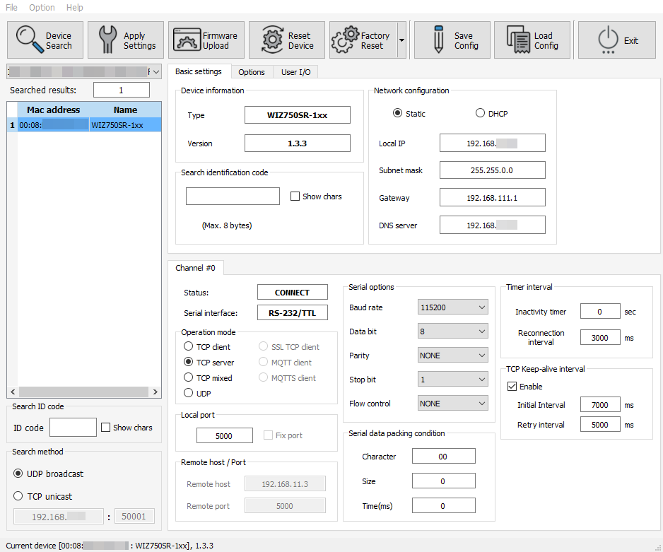
Add-onsZ-Wave JS UIOPEN WEB UISettingsZ-WaveSerial Port as shown in the picture blow. Use the scheme tcp://your-ip:port
Use this space to show useful examples of how a project can be used. Additional screenshots, code examples and demos work well in this space. You may also link to more resources.
For more examples, please refer to the Documentation
See the open issues for a full list of proposed features (and known issues).
Contributions are what make the open source community such an amazing place to learn, inspire, and create. Any contributions you make are greatly appreciated.
If you have a suggestion that would make this better, please fork the repo and create a pull request. You can also simply open an issue with the tag "enhancement". Don't forget to give the project a star! Thanks again!
git checkout -b feature/AmazingFeature)git commit -m 'Add some AmazingFeature')git push origin feature/AmazingFeature)Distributed under the CERN-OHL-P License. See LICENSE for more information. The license for all other sources remains the same and is still valid.
Nikolai Zoller - nikolai.zoller@hotmail.com
Project Link: https://github.com/nikolai2111/RaspberryPi-UART_Ethernet_Adapter
The main concept was initially proposed by an anonymous colleague. The development, production, and sale are carried out with their consent.
Source: Best-README-Template
| Qty | Value | Footprint | References |
|---|---|---|---|
| 4 | MountingHole | MountingHole:MountingHole_3.2mm_M3_DIN965 | H105, H106, H107, H108 |
| 4 | MountingHole | MountingHole:MountingHole_2.7mm_M2.5_DIN965 | H101, H102, H103, H104 |
| 3 | SolderJumper_2_Open | Jumper:SolderJumper-2_P1.3mm_Open_TrianglePad1.0x1.5mm | JP101, JP102, JP103 |
| 2 | 470R | Resistor_SMD:R_0805_2012Metric_Pad1.20x1.40mm_HandSolder | R103, R104 |
| 2 | 5.1k | Resistor_SMD:R_0805_2012Metric_Pad1.20x1.40mm_HandSolder | R101, R102 |
| 2 | Conn_01x06 | Connector_PinSocket_2.54mm:PinSocket_1x06_P2.54mm_Vertical | J102, J104 |
| 2 | GN | LED_SMD:LED_0805_2012Metric_Pad1.15x1.40mm_HandSolder | D101, D102 |
| 1 | 100µF | Capacitor_SMD:C_0805_2012Metric_Pad1.18x1.45mm_HandSolder | C101 |
| 1 | 10µF | Capacitor_SMD:C_0805_2012Metric_Pad1.18x1.45mm_HandSolder | C102 |
| 1 | Barrel_Jack | Connector_User:CUI_PJ-037A_Board-Edge | J108 |
| 1 | Conn_02x05_Odd_Even | Connector_PinHeader_2.54mm:PinHeader_2x05_P2.54mm_Vertical | J105 |
| 1 | Conn_02x06_Odd_Even | Connector_PinSocket_2.54mm:PinSocket_2x06_P2.54mm_Vertical | J101 |
| 1 | LOGO | Drawings_User:elektronik-emblem_10x11.6_solder | G*** |
| 1 | TLV1117-33 | Package_TO_SOT_SMD:SOT-223-3_TabPin2 | U101 |
| 1 | USB4125-GF-A | Connector_User:GCT_USB4125-GF-A | J106 |
| 1 | USB_B_Micro | Connector_USB:USB_Micro-B_Amphenol_10118194_Horizontal | J107 |
protolux-electronics/soleil_hardware
Hardware design files for Soleil, an open source power management and sleep control board for Raspberry Pi


LegendOfRock69/PS2-PSU
A power supply unit for an advanced trimmed SCPH-7900X Model Playstation 2 Slim


eihli/morse-mesh
This is the current hardware source for future Morse Mesh revisions. It is a professionally reviewed redraw of the frozen, fabricated v1 board, not a pin-compatible replacement: notably, KEYIN moved from v1 PA0 to v2…


abendezu10/PulseWatch
Developed a fully functional smartwatch using an STM32 microcontroller, featuring real-time heart rate monitoring.
It measures 67 × 40 mm and has 2 copper layers, 1.6 mm thick.
28 parts, built around the TLV1117-33DCY and USB4125-GF-A. The full list of its parts is on this page, with links to each part's symbol and footprint where PCBKit's library has them.
From the nikolai2111/RaspberryPi-UART_Ethernet_Adapter repository on GitHub, at the commit this page was made from: the board is src/RaspberryPi-UART_Ethernet_Adapter.kicad_pcb and its schematic src/RaspberryPi-UART_Ethernet_Adapter.kicad_sch. PCBKit opens the board in the browser, with nothing to install.
Its repository publishes it under the CERN-OHL-P-2.0 licence: you may reuse it on that licence's terms (keep the author's notice, and for a copyleft licence share your changes alike).