
4 layers65 × 56 mm
Raspberry pi pico 2w
RoyZeng0317/kicad
This is the kicad circuit diagram layout, it's have more layout in here.
83 parts

ROM emulator based on the RP2350B microcontroller
RPROM is an open-source printed circuit board by niklasekstrom, from the niklasekstrom/RPROM repository on GitHub. It is a 4-layer board of 18 × 51 mm with 44 parts on 75 nets, routed with 515 tracks and 78 vias.
It is built around the W25Q32RVXHJQ, TLV1117-33DCY and B5819W SL, with the ABM8-272-T3 among its other parts. Its parts include 21 capacitors, 7 resistors, 4 connectors, 3 ICs and 2 diodes. It belongs with the RP2350 boards of this library.


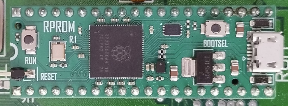
RPROM is a ROM emulator for 16 bit Amiga computers (A500, A600, A2000) based on the RP2350B microcontroller. RPROM was designed in collaboration by Niklas Ekström and Per Bengtsson.
The RPROM board has a 4 MB SPI flash memory. Each ROM image is 512 kB in size, and therefore the 4 MB is divided into eight slots of 512 kB each. The first slot is dedicated to store code and configuration data for the RP2350B. The seven remaining slots are used to store ROM images.
ROM images can be written to flash memory either via USB, or directly from the
Amiga using a program called RPROM. This RPROM program is also used to
switch which slot is the active slot.
This repository contains the hardware, firmware and software for RPROM. The design is intended to be easily understandable and hackable. For example, the firmware is built from a single, roughly 500 lines long, source code file.
RPROM is a CLI command that runs on the Amiga. It has the following
subcommands:
RPROM status prints status information about the deviceRPROM switch <slot> switches the active slot and reboots the AmigaRPROM write <slot> <image> writes the content of file <image> to
slot <slot>RPROM read <slot> <image> reads the content of slot <slot> and saves it
to file <image>RPROM erase <slot> erases slot <slot>Note that ROM images should not be byte swapped.
Both the firmware and ROM images can be programmed from a PC using USB.
Programming is done using the picotool program, which can be downloaded from
https://github.com/raspberrypi/pico-sdk-tools/releases. The RP2350B
microcontroller needs to first be in download mode. To put the RP2350B in
download mode, hold down the BOOTSEL button on the board, and then click the
RUN button. The microcontroller should show up as a USB drive on your PC.
To program the firmware, run picotool load rprom.uf2.
To write a ROM image to a slot, run picotool load <image> -t bin -o <addr>,
where <addr> depends on the slot:
0x100800000x101000000x101800000x102000000x102800000x103000000x10380000There are two revisions of the hardware. The difference between the revisions is quite minor. For rev2, the OE and CE signals have moved from gpio pins 36 and 35 to pins 16 and 17. The benefit of this is that both PIOs with gpiobase=0 and gpiobase=16 can read the OE and CE signals. This in turn results in that using rev2, the time from when the Amiga negates the OE signal to when the RPROM tri-states the data bus is a small number of nanoseconds shorter. In most cases this won't make any difference. In any case, if you are ordering new RPROM PCBs then you likely prefer the latest revision.
In order to compile the firmware you need a recent version (e.g. 2.2.0 or later) of the pico-sdk.
Note that there is a RPROM_REV compile definition in
Firmware/CMakeLists.txt that should be equal to the
hardware revision that the firmware should be used with. Make sure you set it to
the correct value.
This design is free for non-comercial use. The designers take no responsibility for if it doesn't work or if it causes damage to your equipment. If you want to build boards to sell then you need to first ask for approval from the designers.
| References | Value | Footprint | LCSC Part | Quantity |
|---|---|---|---|---|
| C2, C8, C11, C12, C13, C14, C15, C16, C17, C18, C20, C21 | 100n | C_0402_1005Metric | C1525 | 12 |
| C1, C5, C19 | 10u | C_0805_2012Metric | C15850 | 3 |
| C3, C4 | 15p | C_0402_1005Metric | C1548 | 2 |
| C6, C7, C9, C10 | 4.7u | C_0402_1005Metric | C23733 | 4 |
| R2, R4, R6 | 1k | R_0402_1005Metric | C11702 | 3 |
| R7, R8 | 27 | R_0402_1005Metric | C25092 | 2 |
| R1 | 10k | R_0402_1005Metric | C25744 | 1 |
| R3 | 33 | R_0402_1005Metric | C25105 | 1 |
| L1 | 3.3u | L_pol_2016 | C42411119 | 1 |
| D1, D2 | B5819W_SL | D_SOD-123 | C8598 | 2 |
| U1 | RP2350_80QFN | RP2350-QFN-80-1EP_10x10_P0.4mm_EP3.4x3.4mm | C42415655 | 1 |
| U2 | TLV1117-33 | SOT-223-3_TabPin2 | C15578 | 1 |
| Y1 | ABM8-272-T3 | Crystal_SMD_3225-4Pin_3.2x2.5mm | C20625731 | 1 |
| SW1, SW2 | SW_Push | SW_SPST_TS-1088 | C720477 | 2 |
| IC1 | W25Q32RVXHJQ or ZD25WQ32CEIGR | Winbond_USON-8-1EP_3x2mm_P0.5mm_EP0.2x1.6mm | C5258281 | 1 |
| J1 | USB_B_Micro | USB_Micro-B_Amphenol_10103594-0001LF_Horizontal | C428495 | 1 |
| J2, J3 | Conn_01x20 | PinHeader_1x20_P2.54mm_Vertical | - | 2 |
| J4 | Conn_01x01 | PinHeader_1x01_P2.54mm_Horizontal | - | 1 |
The hardware can be cheaply built by JLCPCB using Economic PCBA. Components should be assembled only on the top side, and select that tooling holes are "Added by Customer".
Please pay attention to the orientation of the components if ordering assembly from JLCPCB. Especially pay attention to the orientation of coil L1. When uploading the component placement file to JLCPCB I had to manually fix the orientation of L1 regardless of what the component placement file specified.
| Qty | Value | Footprint | References |
|---|---|---|---|
| 12 | 100n | Capacitor_SMD:C_0402_1005Metric | C2, C8, C11, C12, C13, C14, C15, C16, C17, C18, C20, C21 |
| 3 | 10u | Capacitor_SMD:C_0805_2012Metric | C1, C5, C19 |
| 3 | 1k | Resistor_SMD:R_0402_1005Metric | R2, R4, R6 |
| 2 | 15p | Capacitor_SMD:C_0402_1005Metric | C3, C4 |
| 2 | 27 | Resistor_SMD:R_0402_1005Metric | R7, R8 |
| 2 | 4.7u | RPROM:C_0402_1005Metric_small_pads | C6, C7 |
| 2 | 4.7u | Capacitor_SMD:C_0402_1005Metric | C9, C10 |
| 2 | B5819W_SL | Diode_SMD:D_SOD-123 | D1, D2 |
| 2 | Conn_01x20 | Connector_PinHeader_2.54mm:PinHeader_1x20_P2.54mm_Vertical | J2, J3 |
| 2 | SW_Push | RPROM:SW_SPST_TS-1088 | SW1, SW2 |
| 1 | 10k | Resistor_SMD:R_0402_1005Metric | R1 |
| 1 | 3.3u | RPROM:L_pol_2016 | L1 |
| 1 | 33 | Resistor_SMD:R_0402_1005Metric | R3 |
| 1 | ABM8-272-T3 | Crystal:Crystal_SMD_3225-4Pin_3.2x2.5mm | Y1 |
| 1 | Conn_01x01 | Connector_PinHeader_2.54mm:PinHeader_1x01_P2.54mm_Vertical | J4 |
| 1 | RP2350_80QFN | RPROM:RP2350-QFN-80-1EP_10x10_P0.4mm_EP3.4x3.4mm_ThermalVias | U1 |
| 1 | TLV1117-33 | Package_TO_SOT_SMD:SOT-223-3_TabPin2 | U2 |
| 1 | USB_B_Micro | Connector_USB:USB_Micro-B_Amphenol_10103594-0001LF_Horizontal | J1 |
| 1 | W25Q32RVXHJQ | Package_SON:Winbond_USON-8-1EP_3x2mm_P0.5mm_EP0.2x1.6mm | IC1 |
The 41 most common of 44 parts.
RoyZeng0317/kicad
This is the kicad circuit diagram layout, it's have more layout in here.


bsidestlv/bsidestlv-2025-badge
To solve the challenge you will need to discover a series of flags, hidden inside the badge. Each one will help you unlock the next step in the challenge, to finally reveal the ultimate secret the badge holds.


PhysicsDptAngers/GomuGomuNoDrive
This repository provides open-source hardware designs, physical bench measurement datasets, numerical simulation routines, and real-time DSP emulations for the Rubber Zener clipping topology.


Matheus3007/pcb-lab
PCBs designed entirely as code: Python circuits + KiCad 10 + Freerouting, checked, rendered and ordered assembled from JLCPCB
It measures 18 × 51 mm and has 4 copper layers, 1.6 mm thick.
44 parts, built around the W25Q32RVXHJQ, TLV1117-33DCY, B5819W SL and ABM8-272-T3. The full list of its parts is on this page, with links to each part's symbol and footprint where PCBKit's library has them.
From the niklasekstrom/RPROM repository on GitHub, at the commit this page was made from: the board is Hardware/Rev2/KiCad/RPROM.kicad_pcb and its schematic Hardware/Rev1/KiCad/RPROM.kicad_sch. PCBKit opens the board in the browser, with nothing to install.
Its repository states no licence, so its author keeps all rights: ask niklasekstrom before reusing the design.