
2 layers297.2 × 180.3 mm
 Nickdev8/LedScreen2
# Led Control Board Status: PCB, Firmware, Hardware and examples are Completly done!
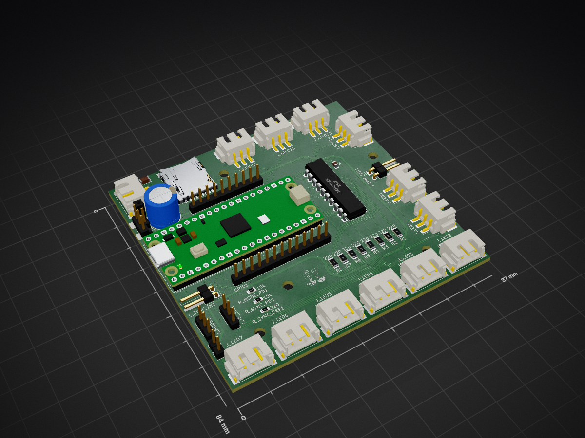
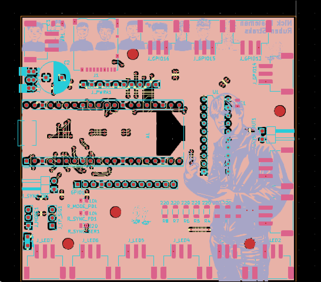
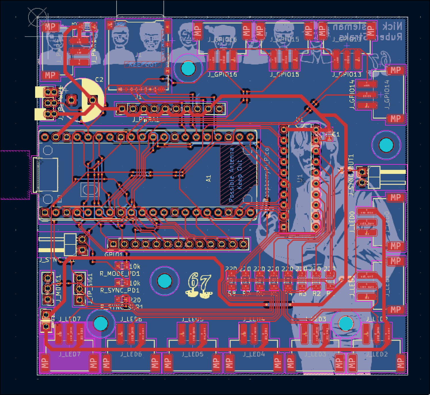
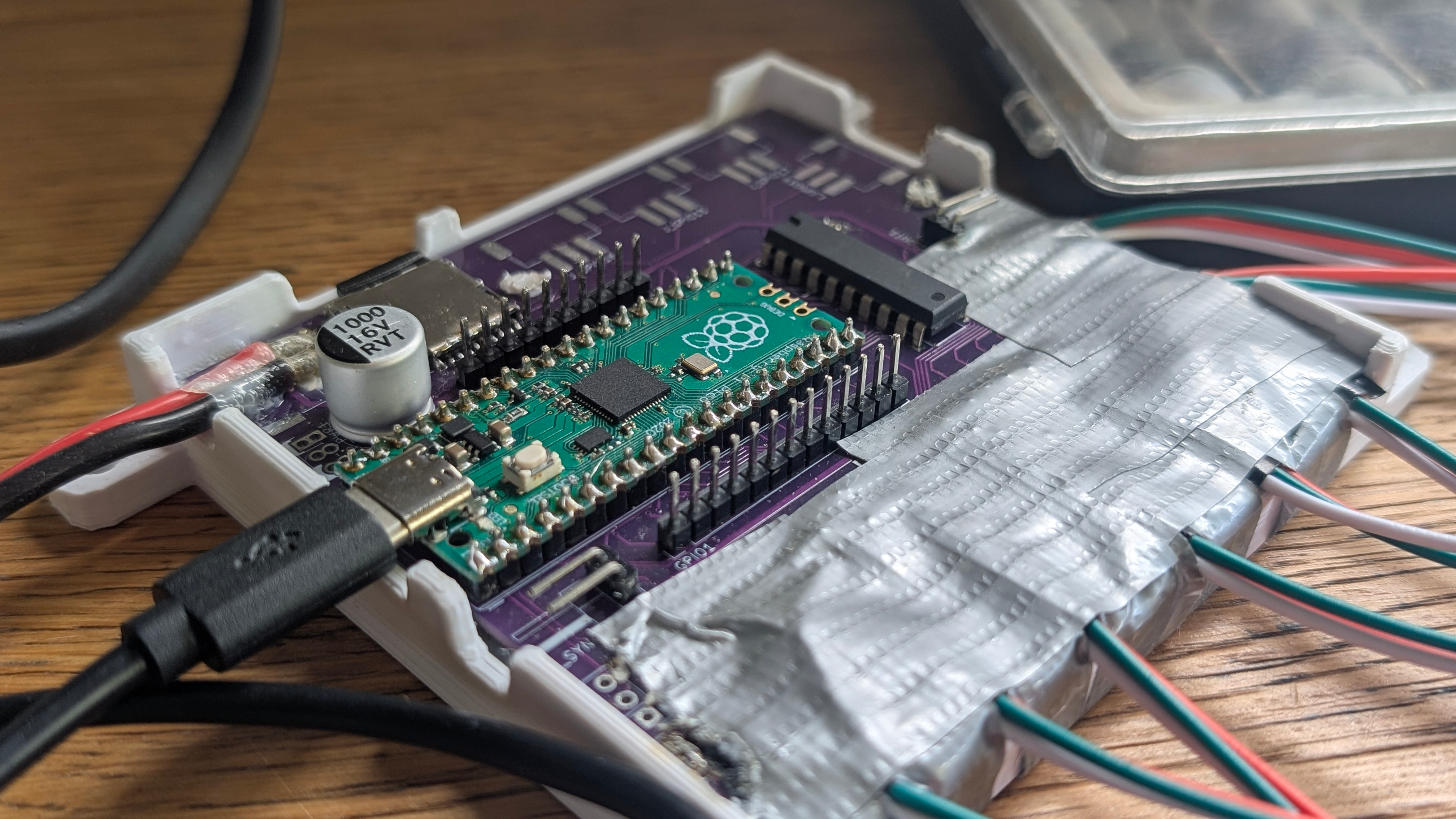
LedScreen is an open-source printed circuit board by Nickdev8, from the Nickdev8/LedScreen repository on GitHub, published under the MIT licence. It is a 2-layer board of 87 × 84 mm with 51 parts on 57 nets, routed with 743 tracks and 104 vias.
It is built around the 74HCT245. Its parts include 8 resistors, 3 capacitors, 1 IC and 1 connector. It belongs with the RP2040 boards of this library.
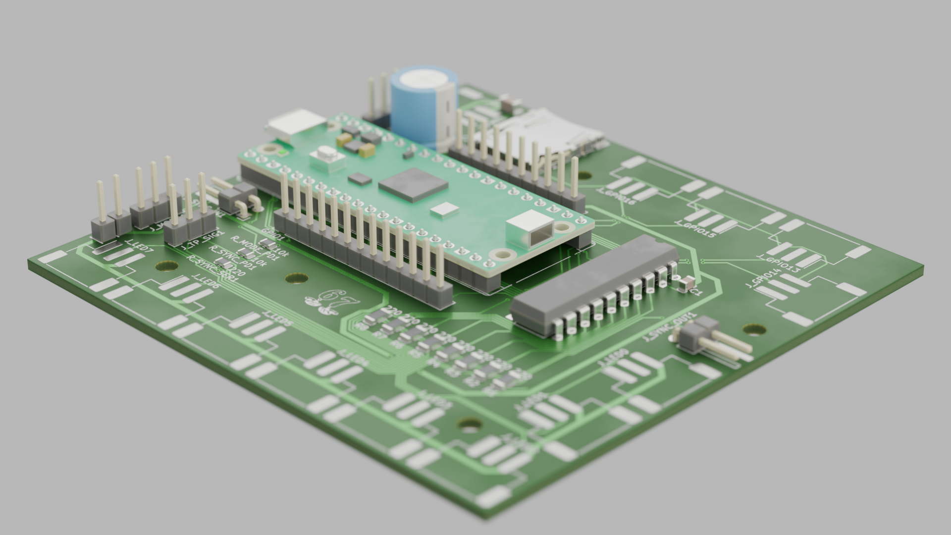
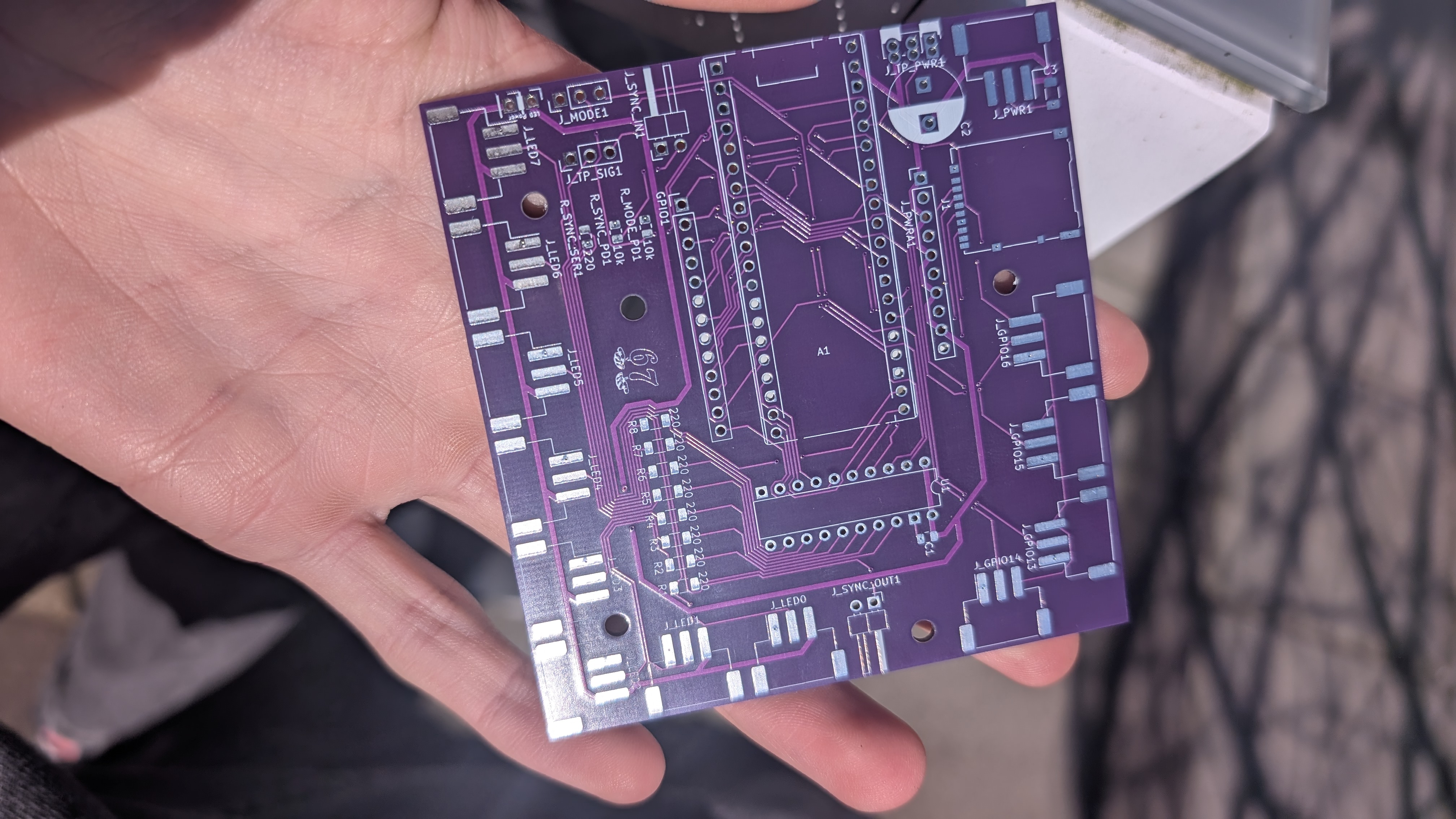
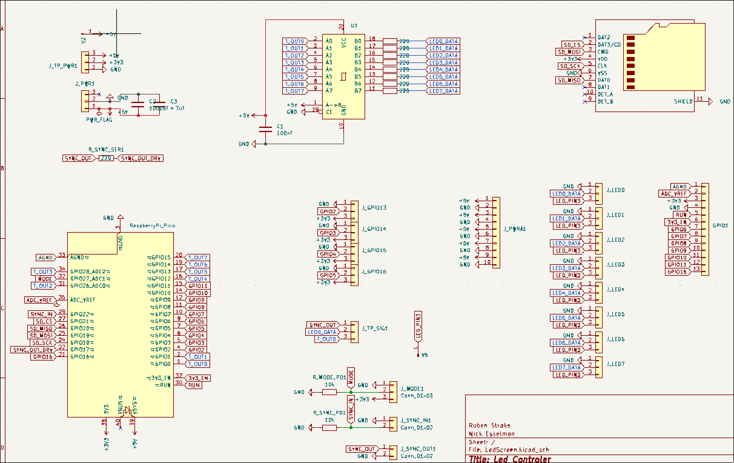
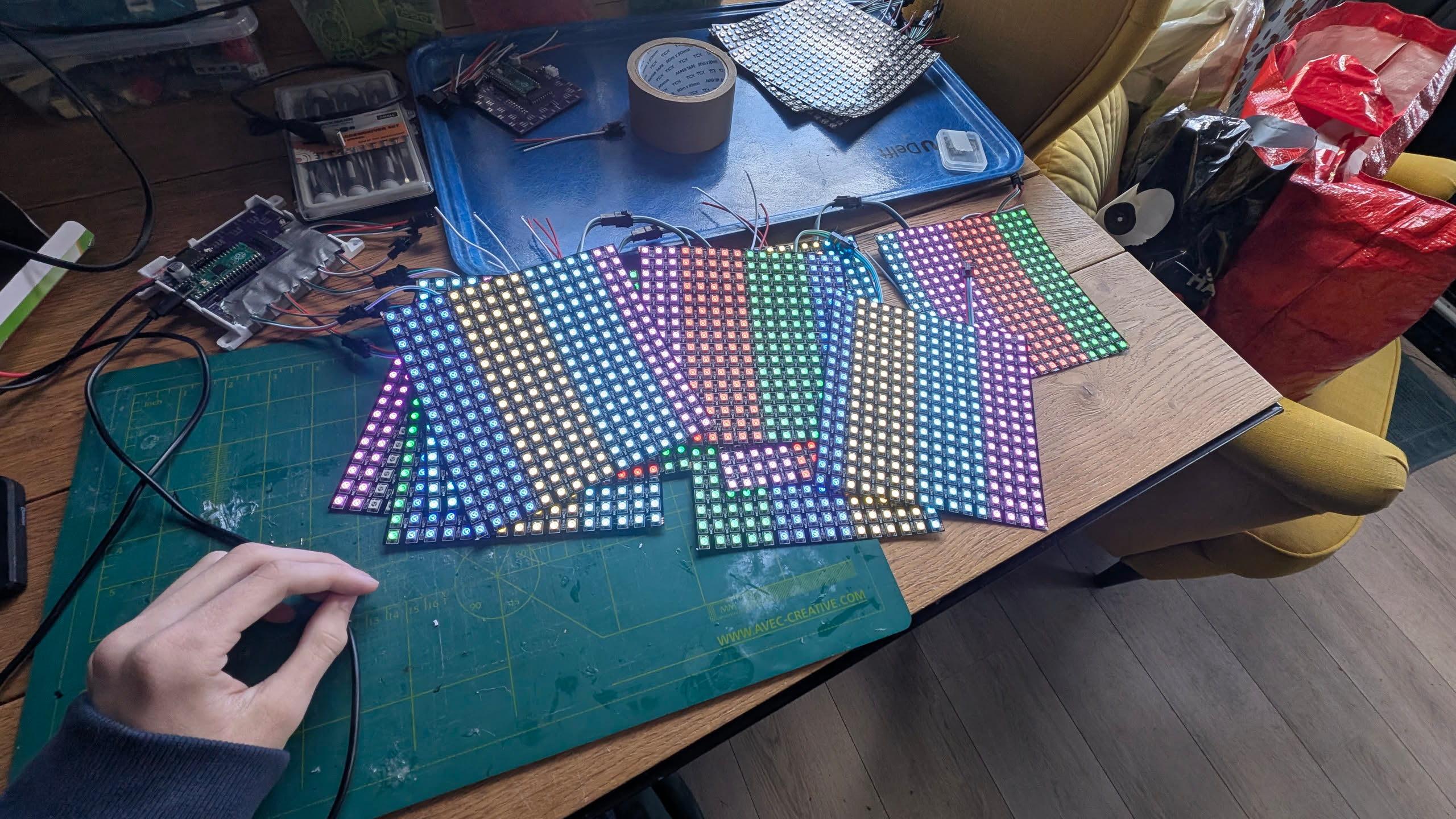
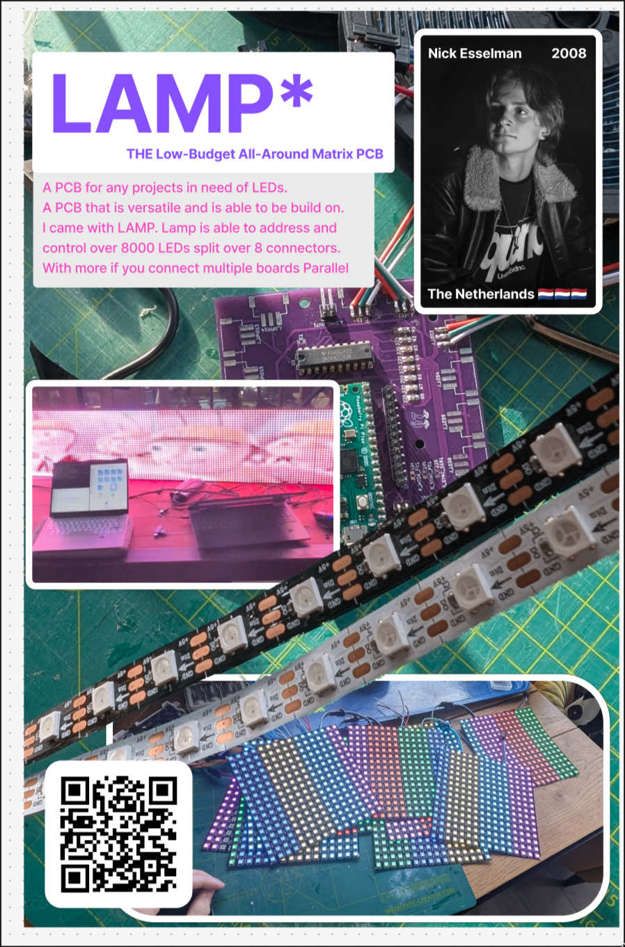
With this board you can control multiple WS2812 LED lines with XLight sequences. The main idea is that I wanted one board that could handle the panel data, SD card playback, and animation syncing between boards. That i all achieved with this pcb.
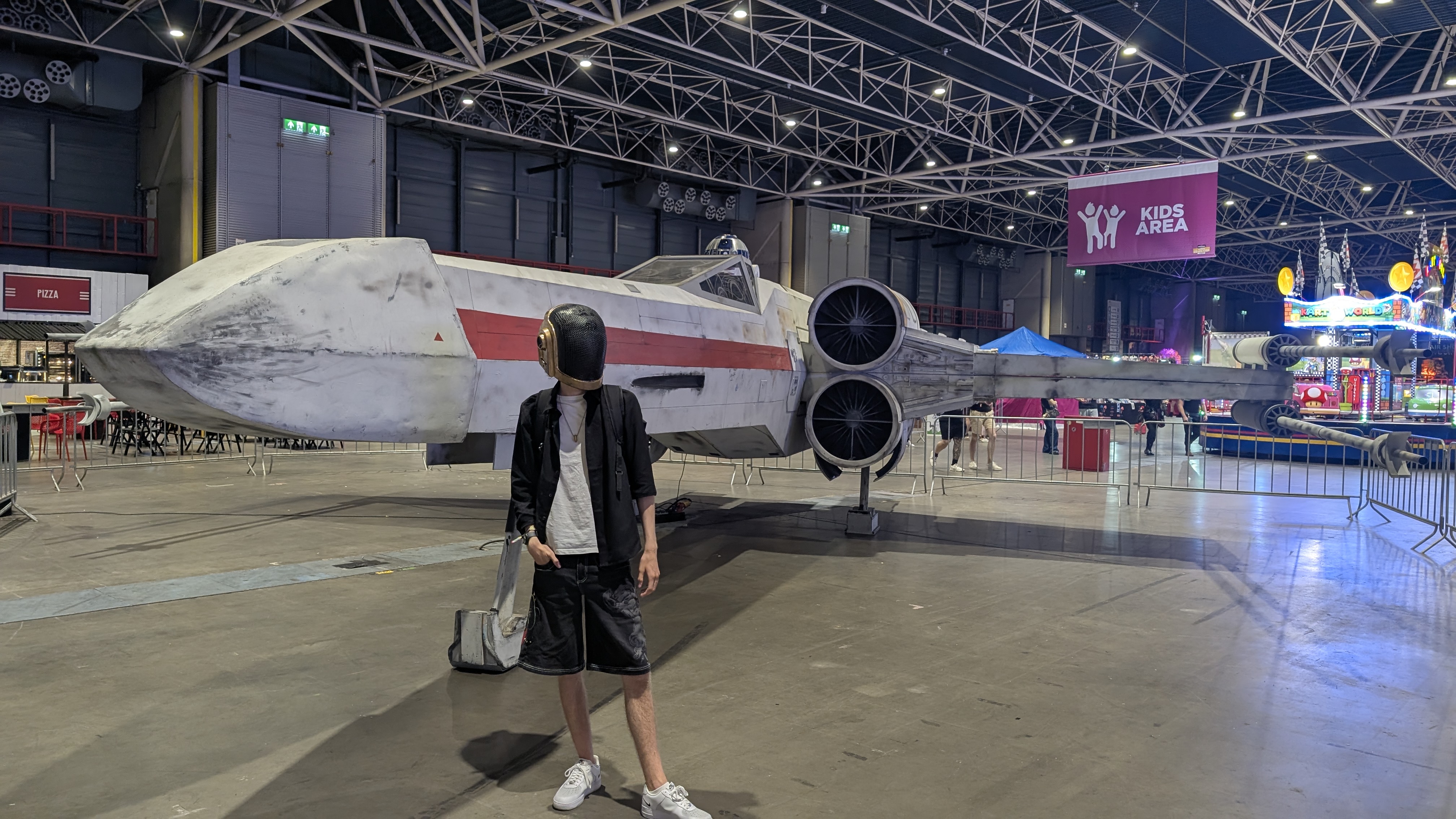
One of my close friends, Ruben, wanted to build a big LED panel project with me so we could display text, animations, and more. After this board is fully working, I also want to use it in 2 daft punk helmets for Comic-Con 2026.
If you want to update the code on the MCU, I would really suggest reading The firmware instuctions. If you want to update the animations on the display, read the animation instuctions.
The basic idea is:
arduino_firmware/Main/..lsa animation files in the SD card root.The Pico runs my own firmware in the arduino_firmware/ folder.
To Install make sure you have the Earle Philhower Arduino-Pico core board library
.lsa files from a FAT32 SD card.startup*.lsa play once at boot in case-insensitive alphabetical order..lsa file then plays in case-insensitive alphabetical order, repeating the complete playlist forever.01_intro.lsa and 02_logo.lsa to control their order.startup_1.lsa are supported.pcb/src/ - PCB soursepcb/exports/LedScreen.pdf - exported schematic PDFpcb/exports/gerber.zip - gerbers bundled for fabrication uploadpcb/Gerber/ - individual gerber outputspcb/bom/ibom.html - interactive BOMmechanical/case/ - case and standoff print filesxlights_project/ - xLights example project for driving the boardscripts/fseq_to_lsa.py - convert xLights FSEQ files to .lsaI also included an xLights example for controlling this board. xLights configuration depends on the final data path used between xLights and the Pico.
Start with a smaller amount of daisy-chained panels per output lane while validating signal integrity and power behavior. Use an external 5V PSU sized for the actual panel count and brightness.
Interactive BOM: cdn.nickesselman.nl
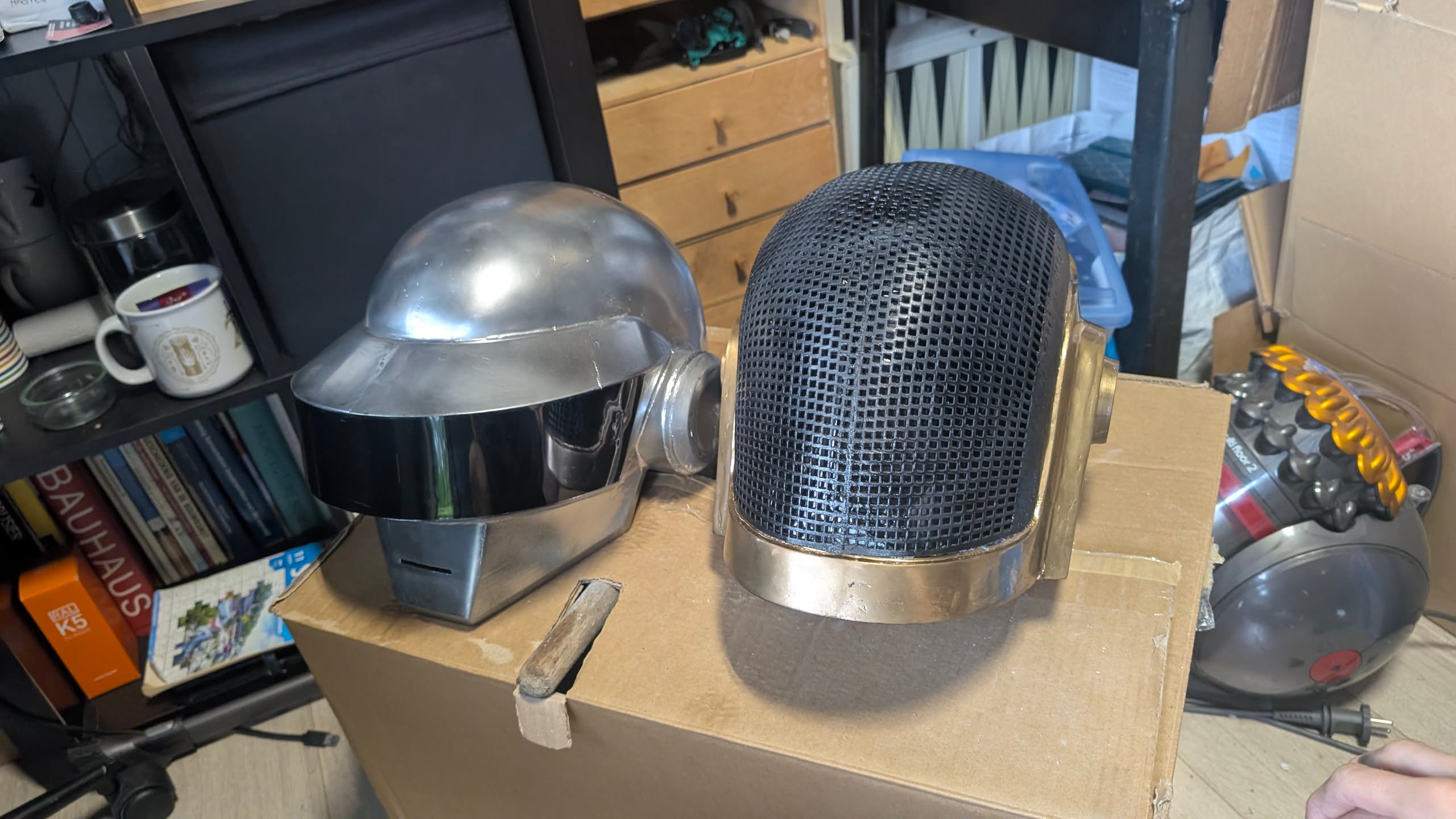
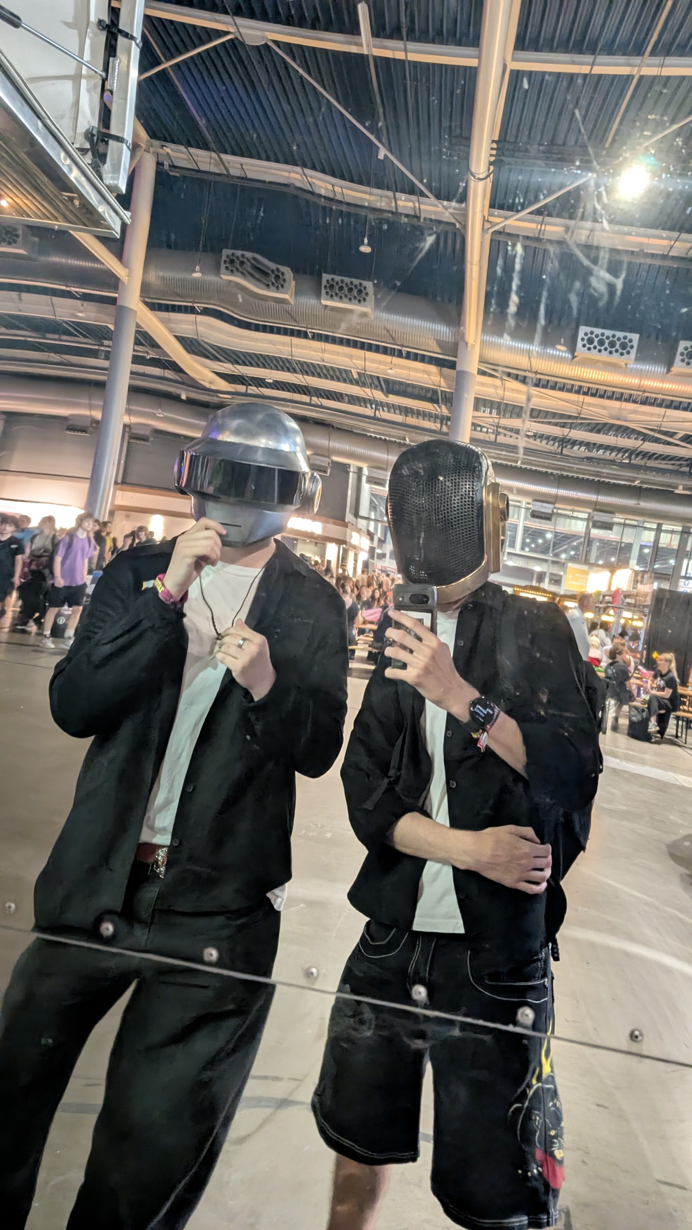
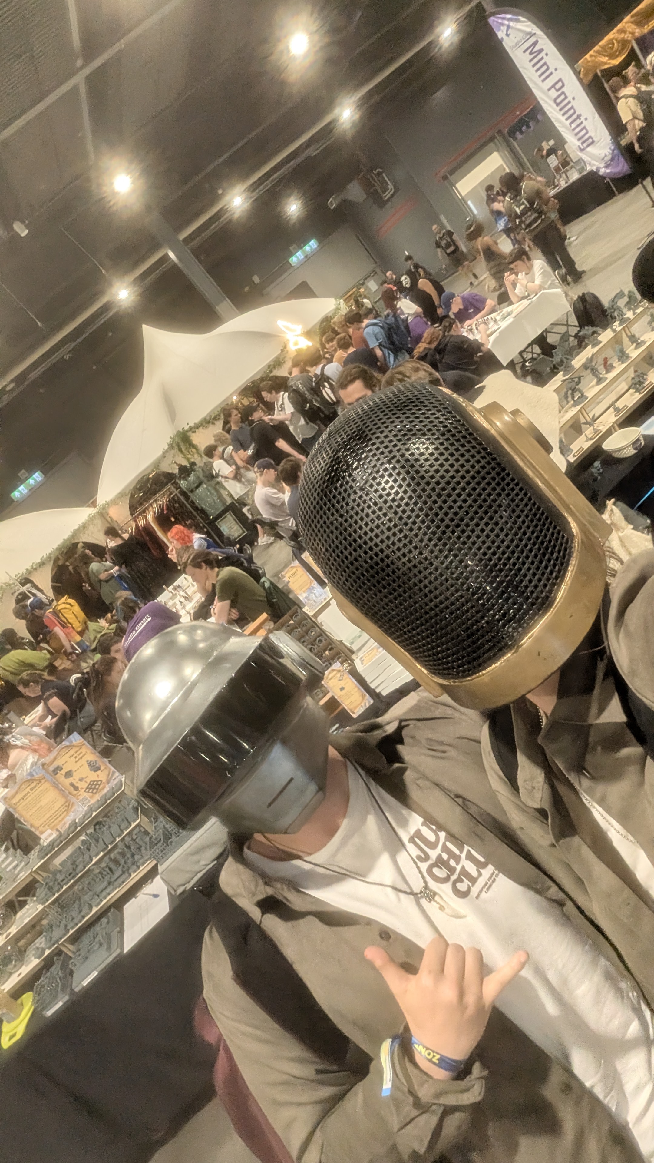
I used this project for 2 Helmets, Guy manual (gold) & Thomas (Silver) all 3d printed in about 200h of print time. and LED strips on the inside for the classic robot screen. Models are in the repo and how i made this you can google and find on instrucables

| Qty | Value | Footprint | References |
|---|---|---|---|
| 9 | Conn_01x03 | Connector_JST:JST_XH_S3B-XH-SM4-TB_1x03-1MP_P2.50mm_Horizontal | J_LED0, J_LED1, J_LED2, J_LED3, J_LED4, J_LED5, J_LED6, J_LED7, J_PWR1 |
| 8 | 220 | Resistor_SMD:R_1206_3216Metric | R1, R2, R3, R4, R5, R6, R7, R8 |
| 4 | LOGO | LOGO | G***, G***, G***, G*** |
| 3 | , , | ||
| 2 | 10k | Resistor_SMD:R_0805_2012Metric | R_MODE_PD1, R_SYNC_PD1 |
| 2 | Conn_01x01_Pin | Connector_PinHeader_2.54mm:PinHeader_1x01_P2.54mm_Vertical | V2, V5 |
| 2 | Conn_01x02 | Connector_PinHeader_2.54mm:PinHeader_1x02_P2.54mm_Horizontal | J_SYNC_IN1, J_SYNC_OUT1 |
| 1 | 1000uF | Capacitor_THT:CP_Radial_D10.0mm_P5.00mm | C2 |
| 1 | 100nF | Capacitor_SMD:C_0805_2012Metric | C1 |
| 1 | 220 | Resistor_SMD:R_0805_2012Metric | R_SYNC_SER1 |
| 1 | 4.7uF | Capacitor_SMD:C_1206_3216Metric | C3 |
| 1 | 74HCT245 | Package_DIP:DIP-20_W7.62mm | U1 |
| 1 | Conn_01x03 | Connector_PinHeader_2.54mm:PinHeader_1x03_P2.54mm_Vertical | J_MODE1 |
| 1 | Conn_01x10 | Connector_PinHeader_2.54mm:PinHeader_1x10_P2.54mm_Vertical | J_PWRA1 |
| 1 | Conn_01x13 | Connector_PinHeader_2.54mm:PinHeader_1x13_P2.54mm_Vertical | GPIO1 |
| 1 | Micro_SD_Card_Det_Hirose_DM3AT | Connector_Card:microSD_HC_Hirose_DM3AT-SF-PEJM5 | J1 |
| 1 | RaspberryPi_Pico | Module:RaspberryPi_Pico_Common_THT | A1 |
| 1 | SPARE_GPIO_13 | Connector_JST:JST_XH_S3B-XH-SM4-TB_1x03-1MP_P2.50mm_Horizontal | J_GPIO13 |
| 1 | SPARE_GPIO_14 | Connector_JST:JST_XH_S3B-XH-SM4-TB_1x03-1MP_P2.50mm_Horizontal | J_GPIO14 |
| 1 | SPARE_GPIO_15 | Connector_JST:JST_XH_S3B-XH-SM4-TB_1x03-1MP_P2.50mm_Horizontal | J_GPIO15 |
| 1 | SPARE_GPIO_16 | Connector_JST:JST_XH_S3B-XH-SM4-TB_1x03-1MP_P2.50mm_Horizontal | J_GPIO16 |
| 1 | TP_PWR | Connector_PinHeader_2.54mm:PinHeader_1x03_P2.54mm_Vertical | J_TP_PWR1 |
| 1 | TP_SIG | Connector_PinHeader_2.54mm:PinHeader_1x03_P2.54mm_Vertical | J_TP_SIG1 |
The 46 most common of 51 parts.
It measures 87 × 84 mm and has 2 copper layers, 1.6 mm thick.
51 parts, built around the 74HCT245. The full list of its parts is on this page, with links to each part's symbol and footprint where PCBKit's library has them.
From the Nickdev8/LedScreen repository on GitHub, at the commit this page was made from: the board is pcb/src/LedScreen.kicad_pcb and its schematic pcb/src/LedScreen.kicad_sch. PCBKit opens the board in the browser, with nothing to install.
Its repository publishes it under the MIT licence: you may reuse it on that licence's terms (keep the author's notice, and for a copyleft licence share your changes alike).


schlae/snark-barker-mca
A Sound Blaster compatible sound card for Micro Channel bus computers

artemisamsx/artemisa
Schematics, PCB designs and HDL simulations to build a 8-bits MSX computer

mecparts/PicoWiFiModem
A Pico W based RS232 <-> WiFi modem with Hayes AT style commands and LED indicators