2 layers57 × 55.2 mm
LogicAnalyzer
gusmanb/logicanalyzer
24 channel, 100Msps logic analyzer hardware and software
10 parts5.1kGPL-3.0

 NevynUK/PicoDebugger26
Hardware designs for Raspberry Pi Pico debug board.
PicoprobeTester is an open-source printed circuit board by NevynUK, from the NevynUK/PicoDebugger repository on GitHub, published under the MIT licence. It is a 2-layer board of 116.7 × 55.7 mm with 10 parts on 70 nets, routed with 183 tracks and 0 vias.
It belongs with the RP2040 boards of this library.
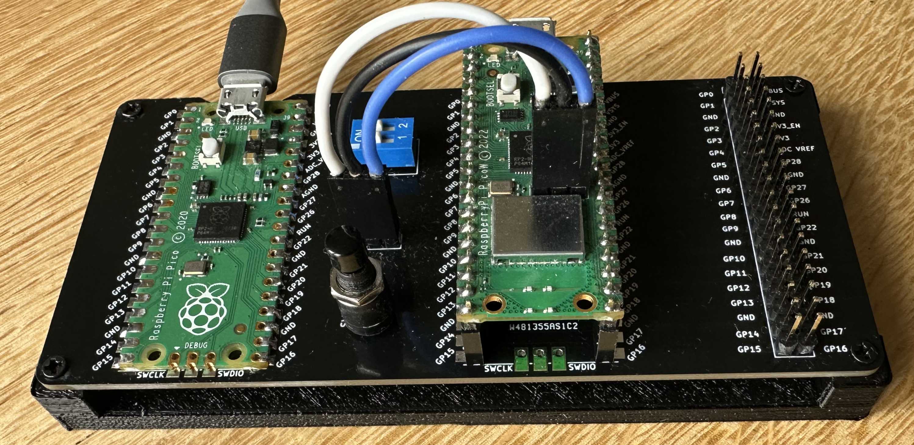
The PicoDebugger project is an extension the Raspberry Pi Foundations PicoProbe project. The basis of the PicoProbe is to use a Raspberry Pi Pico to act as a debug probe for another Pico.
There are two elements to this project:
The aim is to provide a physically stable set up for the debug probe, the target Pico and to also allow connection to hardware under development.
This document will use the following terminology:
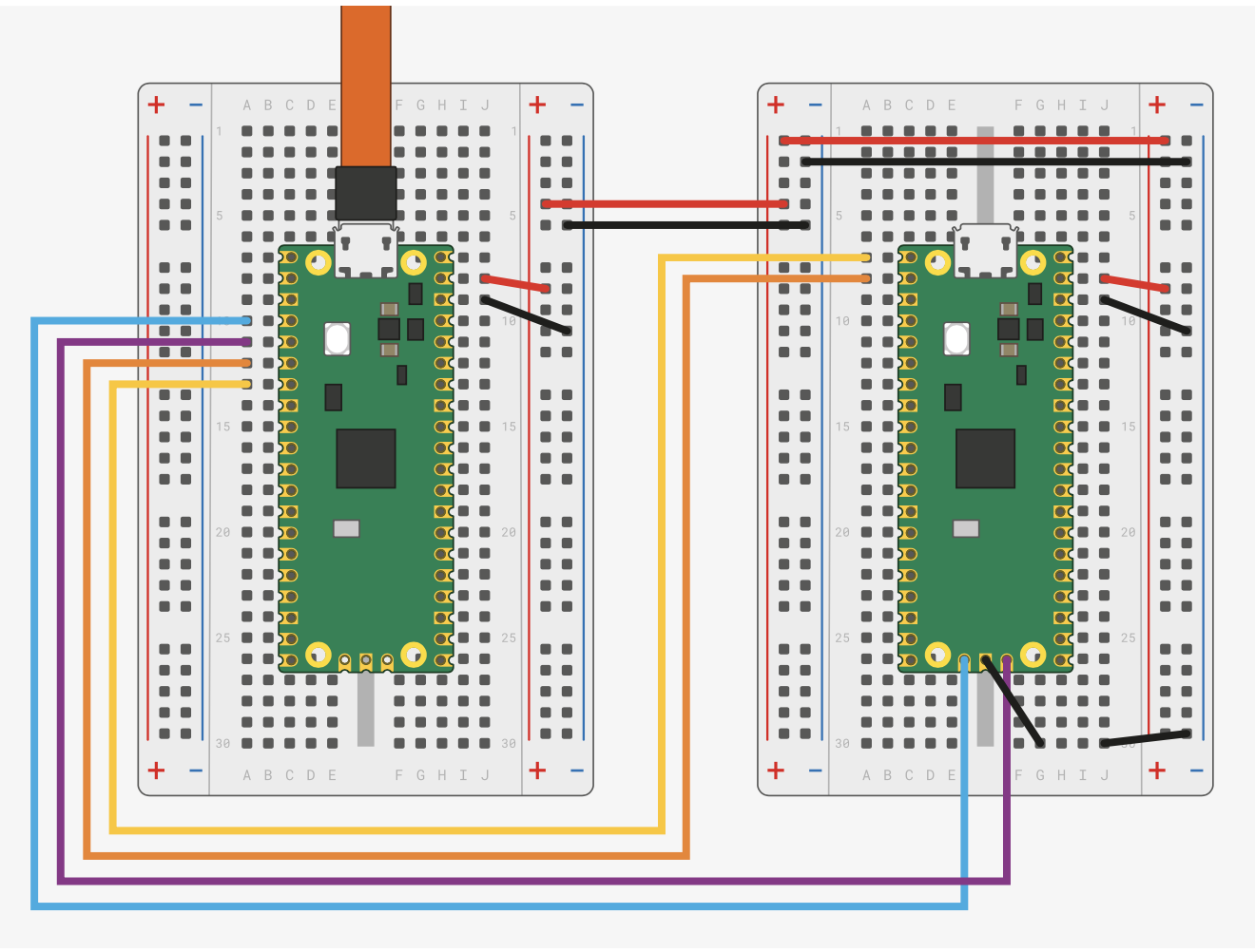
The idea came about as I was developing some software using the NuttX RTOS on the Pico. I had some spare Pico boards available, it was just a case of wiring them up. The Fritzing diagram in the Raspberry Getting Started Guide shows how to connect a Pico as a debug probe to a target Pico:
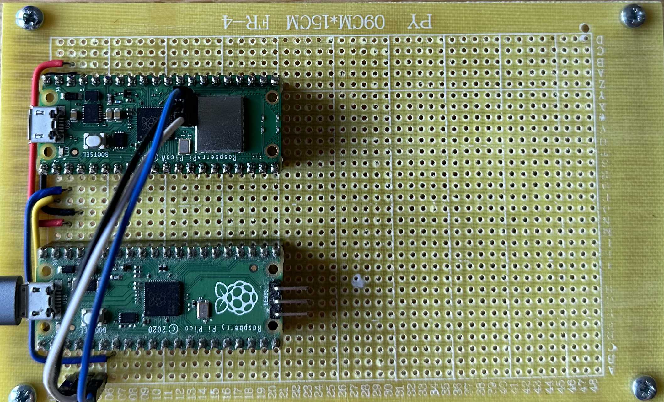
This lead to a quick hack and a development board put together on protoboard:
The next step is to break out KiCad an put together a solution that will allow connections from the target board to additional development hardware.
The Raspberry Pi Foundation have done the hard work by producing the software for the PicoProbe and the PicoDebug probe. You can find more information in the PicoProbe GitHub Repository. This repository contains the links to the documents detailing how to set up a Pico as a debug probe.
The software allows for two types of connection:
SWD allows the host computer to connect to the target board and deploy and debug applications running on the board.
The UART connection will allow the application to generate user messages and also accept input from the host computer.
The PicoDebugger aims to provide the following features:
Thanks to KiCad and PCBWay, a few weeks later we have this:
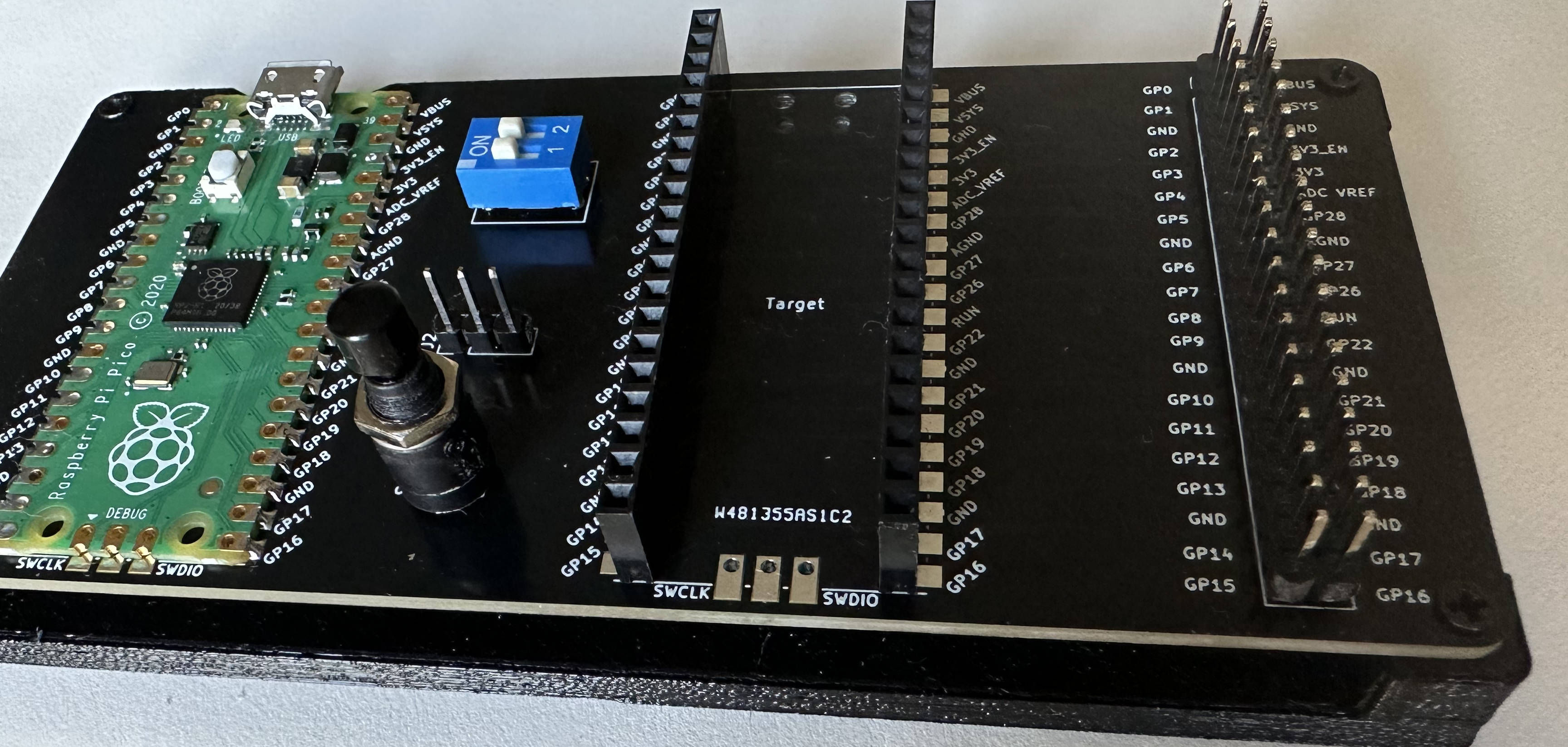
Moving from the left to the right of the board. The left of the board shows the Picoprobe soldered to the board.
The DIP switches allow the two UART lines between the Picoprobe and the target board to be connected / disconnected as required.
The three pin header to be connected to the SWD pins on the Pico or Pico W board.
The reset switch is connected to the reset pin on the target board allowing the target board to be programmed by dragging a UF2 file onto the board.
To the far right there is a 2x20 pin header which matches the pins on the target board. Tis will allow the target board to be connected to development hardware. This could be using individual dupont cables for a small number of connections or using an IDE cable to connect all 40 pins through to a project under development.
The full designs (KiCad 7) of this board are available in the PCB directory.
The image above shows the PicoDebugger board on a 3D printed base. This base keeps the through hole parts from scratching and work surfaces and helps to reduce the possibility of unintended shorts on the exposed pins on the bottom of the board.
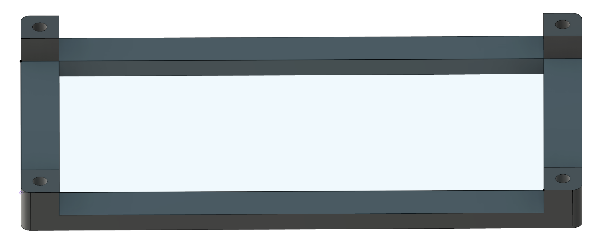
This part is available as a Fusion 360 part in the 3DDesigns folder. This folder also contains the GCode the design. The GCode is intended to be used on an Ender 3 Pro, using PLA. The print has a 50% infill for rigidity.
| Qty | Value | Footprint | References |
|---|---|---|---|
| 4 | MountingHole | MountingHole:MountingHole_2.5mm | H1, H2, H3, H4 |
| 2 | Pico | MCU_RaspberryPi_and_Boards:RPi_Pico_SMD_TH | PicoProbe, Target |
| 1 | External_Connections | Connector_PinHeader_2.54mm:PinHeader_2x20_P2.54mm_Vertical | J1 |
| 1 | Reset_Target | Connector_PinHeader_2.54mm:PinHeader_1x02_P2.54mm_Vertical | Reset |
| 1 | SWD | Connector_PinHeader_2.54mm:PinHeader_1x03_P2.54mm_Vertical | SWD |
| 1 | UART | Button_Switch_THT:SW_DIP_SPSTx02_Slide_9.78x7.26mm_W7.62mm_P2.54mm | UART |
It measures 116.7 × 55.7 mm and has 2 copper layers, 1.6 mm thick.
10 parts. The full list of its parts is on this page, with links to each part's symbol and footprint where PCBKit's library has them.
From the NevynUK/PicoDebugger repository on GitHub, at the commit this page was made from: the board is PCB/PicoprobeTester.kicad_pcb and its schematic PCB/PicoprobeTester.kicad_sch. PCBKit opens the board in the browser, with nothing to install.
Its repository publishes it under the MIT licence: you may reuse it on that licence's terms (keep the author's notice, and for a copyleft licence share your changes alike).
gusmanb/logicanalyzer
24 channel, 100Msps logic analyzer hardware and software

byrantech/laptop
anyon_e, a highly integrated, high end, open source laptop. Attempt the impossible.

joeycastillo/Sensor-Watch
A board replacement for the classic Casio F-91W wristwatch


OLIMEX/OLINUXINO
OLINUXINO is Open Source / Open Hardware, low cost from EUR 24 Linux Industrial grade Single Board Computer capable to operate -25+85C

rusefi/rusefi
rusefi - GPL internal combustion engine control unit

VoronDesign/Voron-Hardware
Cool Hardware designed by the Voron Design group

hoglet67/RGBtoHDMI
Bare-metal Raspberry Pi project that provides pixel-perfect sampling of Retro Computer RGB/YUV video and conversion to HDMI