
2 layers53.8 × 17.8 mm

 nerovny/IV-6-VFD-Clock1
IV-6 VFD Clock based on the STM32f103 MCU
VFD IV6 is an open-source printed circuit board by nerovny, from the nerovny/IV-6-VFD-Clock repository on GitHub. It is a 4-layer board of 110 × 54 mm with 134 parts on 202 nets, routed with 1,406 tracks and 225 vias.
It is built around the STM32F103C8T6, LM2733XMF and MP2307DN-Z, with the TBD62783APG, 74HC04D and LP2985-33DBV among its other parts. Its parts include 39 resistors, 34 capacitors, 19 ICs, 6 diodes and 5 connectors. It belongs with the lEDs and displays boards and the STM32 boards of this library.


This is a basic 6-digit, 7-segment clock based on Soviet ИВ-6 vacuum fluorescent tubes, powered by a widely accessible STM32F103CBT6 microcontroller.
The core concept involves using a single 5V (USB-C) power source and converting the voltage to the 3.3V, 1.2V, and 30–35V levels required to operate the VFD tubes, microcontroller, and logic ICs. These circuits can be seen around the location of the rotary encoder on the right side of the board.
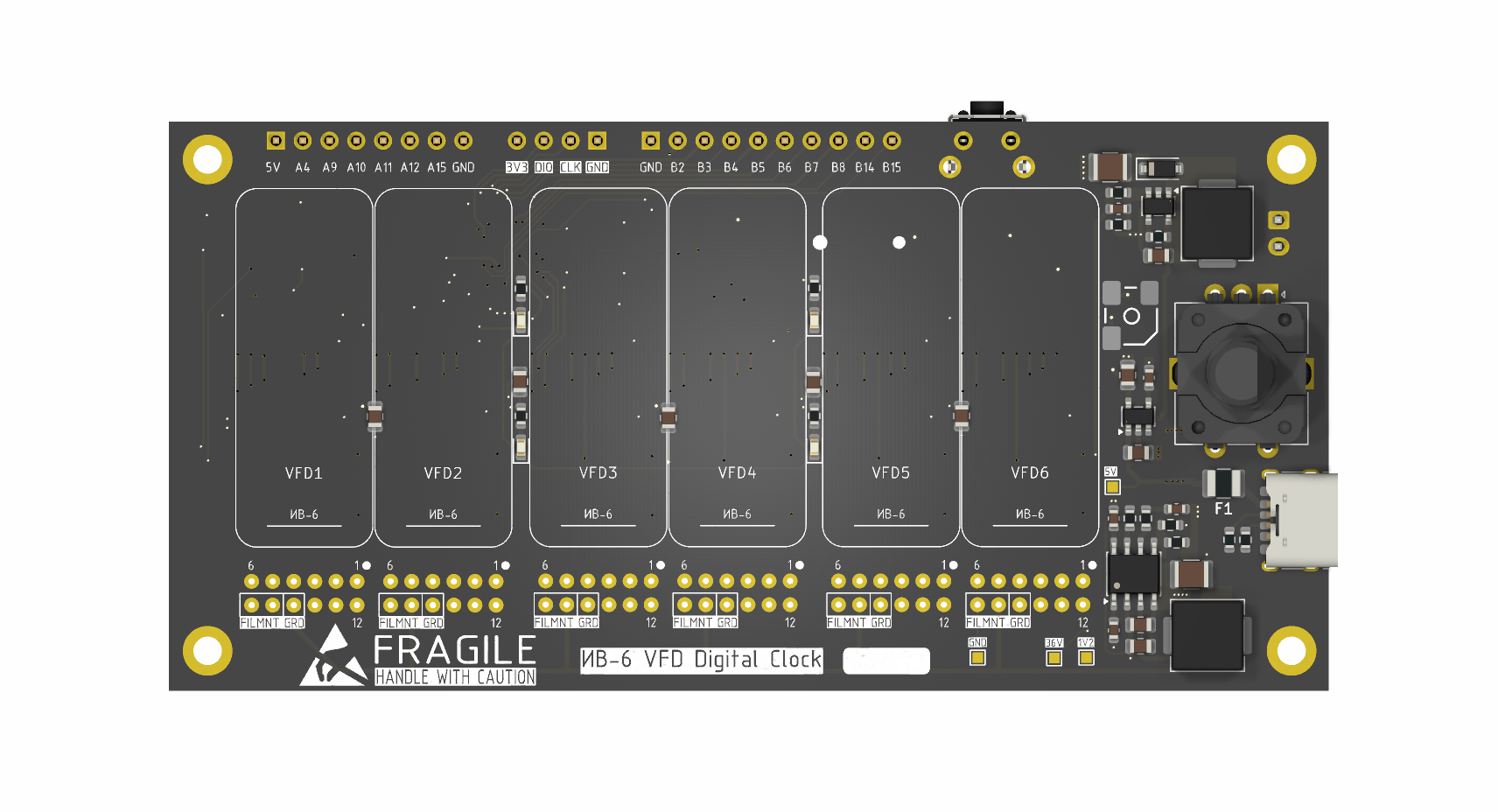
The circuit employs sequential updating of CD4511 BCD-to-7-segment latches and static control of the vacuum fluorescent tubes using TBD62783A eight-channel drivers. The static function of the VFD eliminates the flickering, extends the life of the lamps, but requires much more ICs.
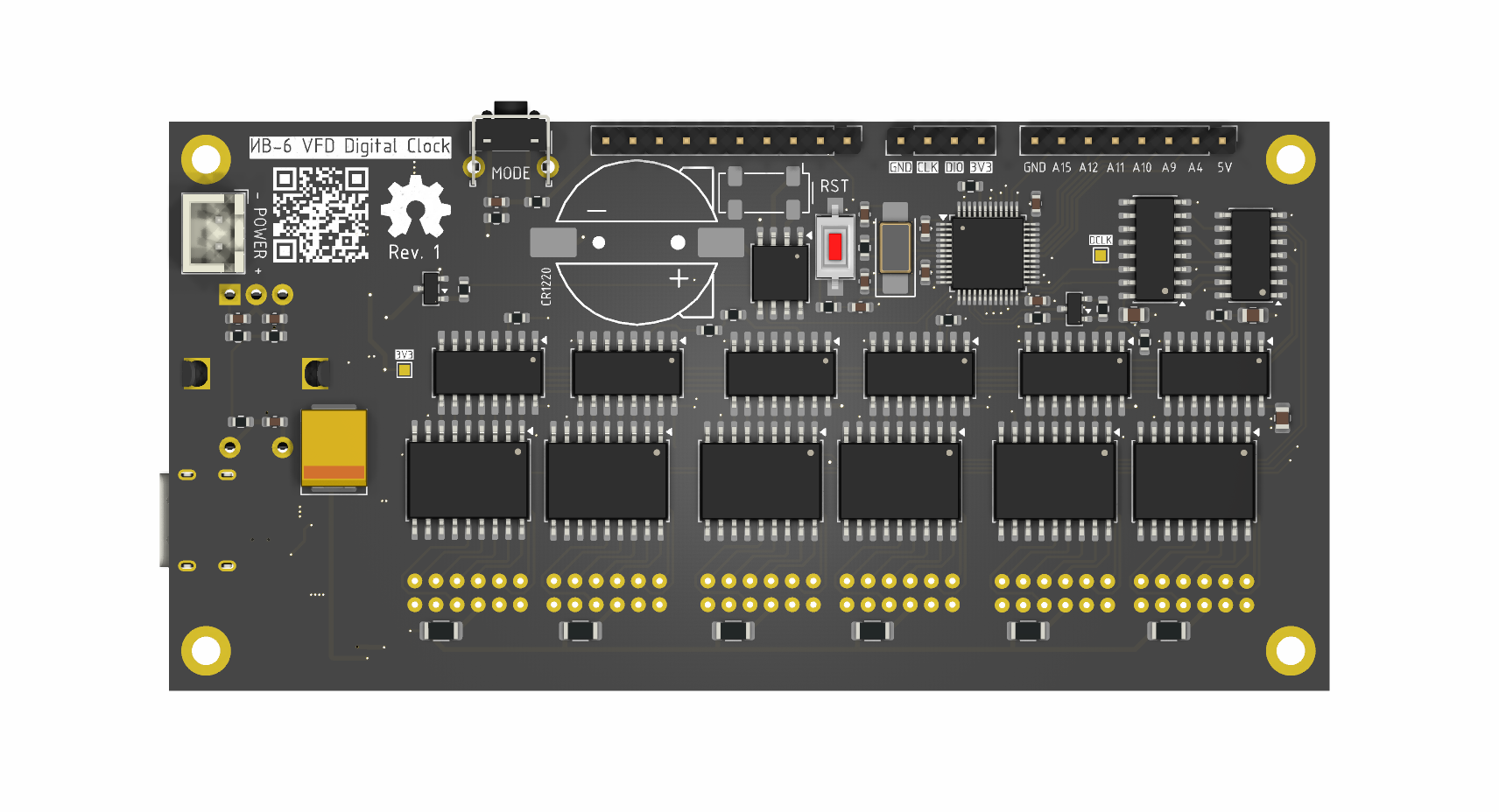
The unused MCU pins and 5v, 3v3 power rails are accessible via the 2.54mm headers and can be used for an additional LEDs, buttons, logic circuitry etc.
The 110x54mm 4-layer board is tight, but definitely doable by hand with the good iron. The road is mastered by the one who walks it.
The latest binary is HERE
Use the onboard SWD header and STM32CubeProgrammer to flash it.
The firmware made with VSCode + PlatformIO using some HAL drivers. Source code is provided: just clone the repo and open the project with PIO VSCode plugin.
| Qty | Value | Footprint | References |
|---|---|---|---|
| 11 | 100n | Capacitor_SMD:C_0603_1608Metric | C2, C3, C7, C8, C16, C19, C21, C22, C24, C25, C33 |
| 10 | 10k | Resistor_SMD:R_0603_1608Metric | R1, R2, R3, R4, R8, R10, R14, R18, R19, R21 |
| 8 | 100n | Capacitor_SMD:C_0805_2012Metric | C23, C26, C27, C28, C29, C30, C31, C32 |
| 7 | 47k | Resistor_SMD:R_0603_1608Metric | R5, R25, R26, R27, R28, R29, R30 |
| 6 | 3k | Resistor_SMD:R_1206_3216Metric | R31, R32, R33, R34, R35, R36 |
| 6 | 4511 | Package_SO:SOP-16_4.4x10.4mm_P1.27mm | U8, U9, U10, U11, U12, U13 |
| 6 | TBD62783A | Package_SO:SOIC-18W_7.5x11.6mm_P1.27mm | U14, U15, U16, U17, U18, U19 |
| 6 | ~ | Library:IV-6_Horizontal | VFD1, VFD2, VFD3, VFD4, VFD5, VFD6 |
| 4 | 4k7 | Resistor_SMD:R_0603_1608Metric | R12, R15, R16, R17 |
| 4 | LED | LED_SMD:LED_0603_1608Metric | D2, D3, D4, D5 |
| 4 | MountingHole | MountingHole:MountingHole_2.7mm_M2.5_DIN965_Pad | H1, H2, H3, H4 |
| 3 | 22p | Capacitor_SMD:C_0402_1005Metric | C17, C18, C34 |
| 3 | 30v | TestPoint:TestPoint_Pad_1.0x1.0mm | TP3, TP4, TP4 |
| 3 | 4k7 | Resistor_SMD:R_0402_1005Metric | R37, R38, R39 |
| 2 | 10n | Capacitor_SMD:C_0603_1608Metric | C6, C12 |
| 2 | 10u 25v | Capacitor_SMD:C_0805_2012Metric | C4, C5 |
| 2 | 5k1 | Resistor_SMD:R_0603_1608Metric | R22, R23 |
| 2 | BC817 | Package_TO_SOT_SMD:SOT-23 | Q1, Q2 |
| 1 | 0 | Resistor_SMD:R_0603_1608Metric | R24 |
| 1 | 0,75A 6V | Fuse:Fuse_1210_3225Metric | F1 |
| 1 | 10u | Capacitor_SMD:C_0805_2012Metric | C9 |
| 1 | 10uH | Inductor_SMD:L_APV_APH0650 | L1 |
| 1 | 13,3k | Resistor_SMD:R_0603_1608Metric | R7 |
| 1 | 18k | Resistor_SMD:R_0603_1608Metric | R13 |
| 1 | 1M | Resistor_SMD:R_0402_1005Metric | R20 |
| 1 | 1V2 | TestPoint:TestPoint_Pad_1.0x1.0mm | TP4 |
| 1 | 1k8 | Resistor_SMD:R_0603_1608Metric | R11 |
| 1 | 1u | Capacitor_SMD:C_0805_2012Metric | C1 |
| 1 | 2,2uH | Inductor_SMD:L_APV_APH0650 | L2 |
| 1 | 220u | Capacitor_Tantalum_SMD:CP_EIA-7360-38_Kemet-E | C20 |
| 1 | 22u 6,3v | Capacitor_SMD:C_1210_3225Metric | C15 |
| 1 | 2u2 | Capacitor_SMD:C_0805_2012Metric | C10 |
| 1 | 2u2 50v | Capacitor_SMD:C_1210_3225Metric | C14 |
| 1 | 32.768 KHz | Crystal:Crystal_SMD_SeikoEpson_MC306-4Pin_8.0x3.2mm | Y1 |
| 1 | 330k | Resistor_SMD:R_0603_1608Metric | R9 |
| 1 | 3V3 | TestPoint:TestPoint_Pad_1.0x1.0mm | TP2 |
| 1 | 3n9 | Capacitor_SMD:C_0603_1608Metric | C11 |
| 1 | 4017 | Package_SO:SOIC-16_3.9x9.9mm_P1.27mm | U7 |
| 1 | 5V | TestPoint:TestPoint_Pad_1.0x1.0mm | TP1 |
| 1 | 6k8 | Resistor_SMD:R_0603_1608Metric | R6 |
| 1 | 74HC04 | Package_SO:SOIC-14_3.9x8.7mm_P1.27mm | U6 |
| 1 | 82p | Capacitor_SMD:C_0603_1608Metric | C13 |
| 1 | 8MHz | Crystal:Crystal_SMD_5032-2Pin_5.0x3.2mm | Y2 |
| 1 | BAV70 | Package_TO_SOT_SMD:SOT-23 | D7 |
| 1 | CLKO | TestPoint:TestPoint_Pad_1.0x1.0mm | TP5 |
| 1 | CR1220 | Library:RSPRO1220 | BT1 |
| 1 | Conn_01x06 | Connector_PinHeader_2.54mm:PinHeader_1x08_P2.54mm_Vertical | J5 |
| 1 | Conn_01x10 | Connector_PinHeader_2.54mm:PinHeader_1x10_P2.54mm_Vertical | J4 |
| 1 | LM2733XMF | Package_TO_SOT_SMD:SOT-23-5 | U3 |
| 1 | LP2985-3.3 | Package_TO_SOT_SMD:SOT-23-5 | U1 |
| 1 | MBR0530 | Diode_SMD:D_SOD-123 | D1 |
| 1 | MODE | Button_Switch_THT:SW_Tactile_SPST_Angled_PTS645Vx39-2LFS | SW2 |
| 1 | MP2307 | Package_SO:SOIC-8_3.9x4.9mm_P1.27mm | U2 |
| 1 | PCF8563T | Package_SO:SOIC-8_3.9x4.9mm_P1.27mm | U20 |
| 1 | Power | Connector_JST:JST_XH_B2B-XH-A_1x02_P2.50mm_Vertical | J3 |
| 1 | RotaryEncoder_Switch_MP | Rotary_Encoder:RotaryEncoder_Alps_EC12E-Switch_Vertical_H20mm | SW1 |
| 1 | STM32F103C8T6 | Package_QFP:LQFP-48_7x7mm_P0.5mm | U5 |
| 1 | SWD | Connector_PinHeader_2.54mm:PinHeader_1x04_P2.54mm_Vertical | J2 |
| 1 | SW_SPST | Button_Switch_SMD:SW_SPST_CK_RS282G05A3 | RESET1 |
| 1 | USB_C | Connector_USB:USB_C_Receptacle_HRO_TYPE-C-31-M-17 | J1 |
| 1 | ~ | Library:HCT5020 | BZ1 |
The 132 most common of 134 parts.


AidanHockey5/MegaBlaster2
The latest iteration of my hardware Sega Genesis/Megadrive Video Game Music Player

Maniak003/ScintMonitor
Scintilation monitor with window comparator. Device with Ethernet interface


Neumi/open_echo
Open Source echo sounder / depth sounder / SONAR for bathymetry and research. Arduino based and compatible.

alxhoff/Nixie-tube-clock
Firmware for a nixie tube clock based on STM32 hal libraries

luftaquila/monolith
DIY wireless real-time datalogging platform for Student Formula and Baja.
It measures 110 × 54 mm and has 4 copper layers, 1.6 mm thick.
134 parts, built around the STM32F103C8T6, LM2733XMF, MP2307DN-Z and TBD62783APG. The full list of its parts is on this page, with links to each part's symbol and footprint where PCBKit's library has them.
From the nerovny/IV-6-VFD-Clock repository on GitHub, at the commit this page was made from: the board is hardware/VFD_IV6.kicad_pcb and its schematic hardware/VFD_IV6.kicad_sch. PCBKit opens the board in the browser, with nothing to install.
Its repository states no licence, so its author keeps all rights: ask nerovny before reusing the design.