2 layers86 × 33 mm
MicroCurrent
reivax-boucoi/PCB_Kicad
Repo for all my home projects involving PCBs developped with Kicad
31 parts1
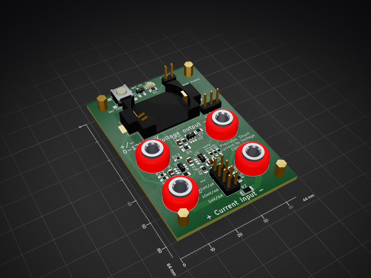
 NerdyProjects/ucurrent-clone7
This repository holds a clone of the ucurrent gold from https://www.eevblog.com/projects/ucurrent/
Ucurrent is an open-source printed circuit board by NerdyProjects, from the NerdyProjects/ucurrent-clone repository on GitHub. It is a 2-layer board of 44 × 64 mm with 40 parts on 23 nets, routed with 205 tracks and 8 vias.
It is built around the MAX4239AUT and LMV321. Its parts include 16 resistors, 7 connectors, 4 capacitors, 4 ICs and 2 diodes.


This repository holds a clone of the ucurrent gold from https://www.eevblog.com/projects/ucurrent/
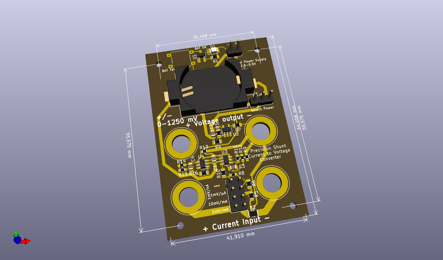
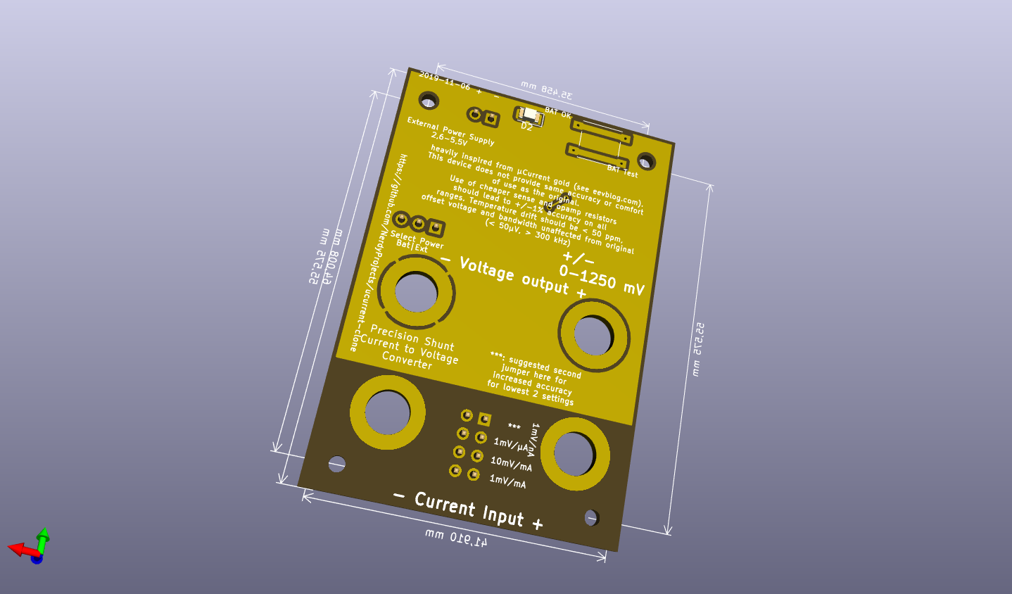
Range selection happens by putting a jumper on the selector panel. To change the range without powering of the device under test, just use a second jumper and remove the first one later. The proposed sense resistors are:
| Count | Reference | Description | Purpose | Digikey | Reichelt | Price (total) |
|---|---|---|---|---|---|---|
| 1 | BT1 | CR2032 Battery Holder SMD | 1060K-ND | 1,05 € | ||
| 1 | - | Case 64x44x32mm | RND 455-00094 | 1,01 € | ||
| 2 | C1, C2 | Capacitor X7R 100 nF 0805 | blocking cap | 0,05 € | ||
| 2 | C3, C4 | Capacitor, 10 pF 0805 | opamp stabilization | 0,05 € | ||
| 2 | J2, J3, J6, J7 | Banana Jack 4mm red | measurement connections | BIL 20 RT, BB 4 RT BD | 1,76 €, 0,64 € | |
| 2 | J2, J3, J6, J7 | Banana Jack 4mm black | measurement connections | BIL 20 SW, BB 4 SW BD | 1,76 €, 0,64 € | |
| 1 | J4 | jumper terminal, 1x03, 2,54mm | power selector | 0,05 € | ||
| 1 | J1 | jumper or screw terminal, 1x02, 2,54mm | external power | 0,20 € | ||
| 1 | J5 | double row connector, 02x04, 2,54mm | measurement range selection | 0,10 € | ||
| 4 | R1, R7, R10, R16 | Resistor 270 ohms 0805 (any) | 0,05 € | |||
| 1 | R2 | Resistor 10 mOhms 1206 <= 1%, TC < 100 ppm | Shunt for 1mV/mA range | ERJ-6CWDR010V (0,5%, 75ppm) | 0,75 € | |
| 2 | R3, R4 | Resistor 100 kOhms 0805 (any) | voltage divider for VGND | 0,02 € | ||
| 1 | R5 | Resistor 90 mOhms 0805 <= 1%, TC < 100 ppm | Shunt for 10mV/mA range | WSL0805R0900FEA (1%, 75ppm) | 0,85 € | |
| 1 | R6 | Resistor 10 Ohms 0805 <= 1%, TC < 100 ppm | Shunt for 1mV/µA range | RR12Q10DCT-ND (0,5%, 50ppm) | 0,13 € | |
| 1 | R8 | Resistor 10 kOhms 0603 <= 1%, TC < 100 ppm | Shunt for 1mV/nA range | SPR-0603 10,0K (0,1%, 25ppm) | 0,25 € | |
| 2 | R9, R13 | Resistor 1 kOhms 0603 as precise as possible | amplifier feedback | SPR-0603 1,00K (0,1%, 25ppm) | 0,50 € | |
| 2 | R11, R14 | Resistor 6,8 kOhms 0603 as precise as possible | amplifier feedback | SPR-0603 6,80K (0,1%, 25ppm) | 0,50 € | |
| 2 | R12, R15 | Resistor 2,2 kOhms 0603 as precise as possible | amplifier feedback | SPR-0603 2,20K (0,1%, 25ppm) | 0,50 € | |
| 1 | SW1 or SW2 | Pushbutton 6mm | battery check | RND 210-00207 | 0,12 € | |
| 1 | U1 | TPS3839 | Power supply supervisor 2,65 V | TPS3839DBZ | 0,74 € | |
| 1 | U2 | LMV321 | opamp (generic) for VGND | LMV321LILT | 0,43 € | |
| 2 | U3, U4 | MAX4239AUT | ultra low offset/drift/noise opamp for measurement amplification | MAX4239AUT | 5,30 € | |
| SUM: 13,93 € |
Current usage of other ucurrent clone at 2.7V: 1.004 mA (via Multimeter) or 1.04 mA (via ucurrent clone @ 1mV/µA). Unfortunately, there is a bunch of problems, which also seem to exist in the original ucurrent, but have different levels of manifestation.
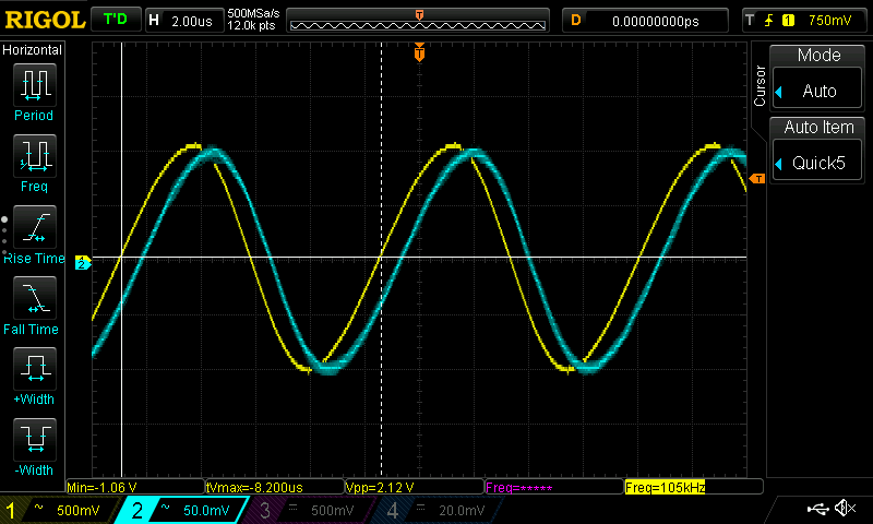
Some scope shots, CH1 voltage over a 10 kOhm resistor, CH2 output voltage of ucurrent clone
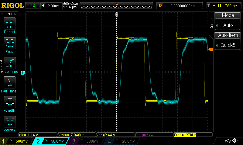
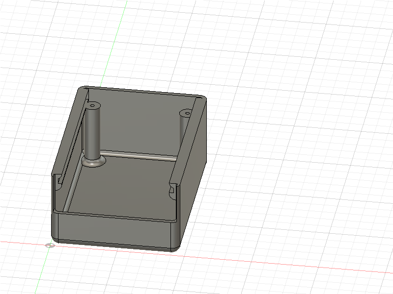
A draft for a 3d printable case is there as well. There is some space for a 2x AAA batteryholder below the PCB but it does not contain any mounting utilities for that.
| Qty | Value | Footprint | References |
|---|---|---|---|
| 4 | 270 | Resistor_SMD:R_0805_2012Metric_Pad1.15x1.40mm_HandSolder | R1, R7, R10, R16 |
| 4 | MountingHole | MountingHole:MountingHole_2.2mm_M2 | H1, H2, H3, H4 |
| 2 | 100k | Resistor_SMD:R_0805_2012Metric_Pad1.15x1.40mm_HandSolder | R3, R4 |
| 2 | 100n | Capacitor_SMD:C_0805_2012Metric_Pad1.15x1.40mm_HandSolder | C1, C2 |
| 2 | 10pf | Capacitor_SMD:C_0805_2012Metric_Pad1.15x1.40mm_HandSolder | C3, C4 |
| 2 | 1k 0.1% | Resistor_SMD:R_0603_1608Metric_Pad1.05x0.95mm_HandSolder | R9, R13 |
| 2 | 2k2 0.1% | Resistor_SMD:R_0603_1608Metric_Pad1.05x0.95mm_HandSolder | R12, R15 |
| 2 | 6k8 0.1% | Resistor_SMD:R_0603_1608Metric_Pad1.05x0.95mm_HandSolder | R11, R14 |
| 2 | BAT_TEST | Button_Switch_SMD:SW_Push_1P1T_NO_6x6mm_H9.5mm | SW1, SW2 |
| 2 | GREEN | LED_SMD:LED_1206_3216Metric | D1, D2 |
| 2 | MAX4239AUT | Package_TO_SOT_SMD:SOT-23-6_Handsoldering | U3, U4 |
| 1 | 10R 1% | Resistor_SMD:R_0805_2012Metric_Pad1.15x1.40mm_HandSolder | R6 |
| 1 | 10k 1% | Resistor_SMD:R_0603_1608Metric_Pad1.05x0.95mm_HandSolder | R8 |
| 1 | 10m 1% | Resistor_SMD:R_1206_3216Metric_Pad1.42x1.75mm_HandSolder | R2 |
| 1 | 90m 1% | Resistor_SMD:R_0805_2012Metric_Pad1.15x1.40mm_HandSolder | R5 |
| 1 | Battery_Cell | Battery:BatteryHolder_Keystone_1060_1x2032 | BT1 |
| 1 | Conn_01x02 | Connector_PinHeader_2.54mm:PinHeader_1x02_P2.54mm_Vertical | J1 |
| 1 | IN_N | Connector:Banana_Jack_1Pin | J3 |
| 1 | IN_P | Connector:Banana_Jack_1Pin | J2 |
| 1 | LMV321 | Package_TO_SOT_SMD:SOT-23-5_HandSoldering | U2 |
| 1 | OUT_N | Connector:Banana_Jack_1Pin | J7 |
| 1 | OUT_P | Connector:Banana_Jack_1Pin | J6 |
| 1 | POWER | Connector_PinHeader_2.54mm:PinHeader_1x03_P2.54mm_Vertical | J4 |
| 1 | Select | Connector_PinHeader_2.54mm:PinHeader_2x04_P2.54mm_Vertical | J5 |
| 1 | TPS3839DBZ | Package_TO_SOT_SMD:SOT-23_Handsoldering | U1 |
It measures 44 × 64 mm and has 2 copper layers, 1.6 mm thick.
40 parts, built around the MAX4239AUT and LMV321. The full list of its parts is on this page, with links to each part's symbol and footprint where PCBKit's library has them.
From the NerdyProjects/ucurrent-clone repository on GitHub, at the commit this page was made from: the board is ucurrent.kicad_pcb. PCBKit opens the board in the browser, with nothing to install.
Its repository states no licence, so its author keeps all rights: ask NerdyProjects before reusing the design.
reivax-boucoi/PCB_Kicad
Repo for all my home projects involving PCBs developped with Kicad

EOSCogniton/ELIZ-2022
Le Git Artemiz de l'EPSA. Contient le Catia, ainsi que la documentation en cours et quelques modèles.

antonloof/eta_rotary_coffe_dispenser
Dagny 2.0. Även kännd som ETAs kaffedispenser med gammal teknik


0x23/nmWave-Interferometer
An Open Source Interferometer for Accurate Distance Measurements

KarlK90/yaemk-split-kb
5x8 Split keyboard with thumb-clusters, rotary encoders and oleds.

lucysrausch/sony-scopeman
Hardware Design files of a replacement mainboard for the Sony Watchman FD-10. This turns it into a bluetooth and WiFi-enabled vector display.
