Skip to the content
2 layers30.5 × 58.5 mmHemlarm, the printed circuit board in 3D

A local smart home alarm system built with Raspberry Pi Zero WH, including PIR sensing, LED and buzzer feedback, Zigbee/MQTT door monitoring, camera integration, a web dashboard, and custom PCB design.

Size
30.5 × 58.5 mm
Copper layers
2
Thickness
1.6 mm
Parts
6
Nets
43
Pads
52
Tracks, vias
23, 0
Pours
1
Routed
Yes
KiCad
KiCad 9.0 (file 20241229)
Created
26 May 2026
Updated
11 Jun 2026

Overview

Hemlarm is an open-source printed circuit board by neez11, from the neez11/Smart-Home-Alarm repository on GitHub. It is a 2-layer board of 30.5 × 58.5 mm with 6 parts on 43 nets, routed with 23 tracks and 0 vias.

Its parts include 4 connectors and 2 resistors. It belongs with the home automation and IoT and radio and wireless boards and the Raspberry Pi (Linux) boards of this library.

README

README.md

Smart Home Alarm

A local smart home alarm built with Raspberry Pi Zero WH, featuring PIR motion detection, LED and buzzer alarm feedback, Zigbee/MQTT door monitoring, camera support, a web dashboard and custom PCB design.


Development

This project was developed as a group project in Electrical Engineering.

Contributors:


Overview

This project is a smart home alarm prototype designed to run locally without cloud services.
It combines embedded hardware, wireless communication, backend logic, a web-based dashboard, PCB design, and a 3D-printed enclosure into one complete system.

The system is built around a Raspberry Pi Zero WH and can:

  • detect motion using a PIR sensor
  • detect door/window events using a Zigbee sensor
  • trigger local alarm feedback using LED and buzzer
  • log events in the backend
  • show live status in a web dashboard
  • display a camera feed during alarm events
  • run locally without relying on external cloud platforms

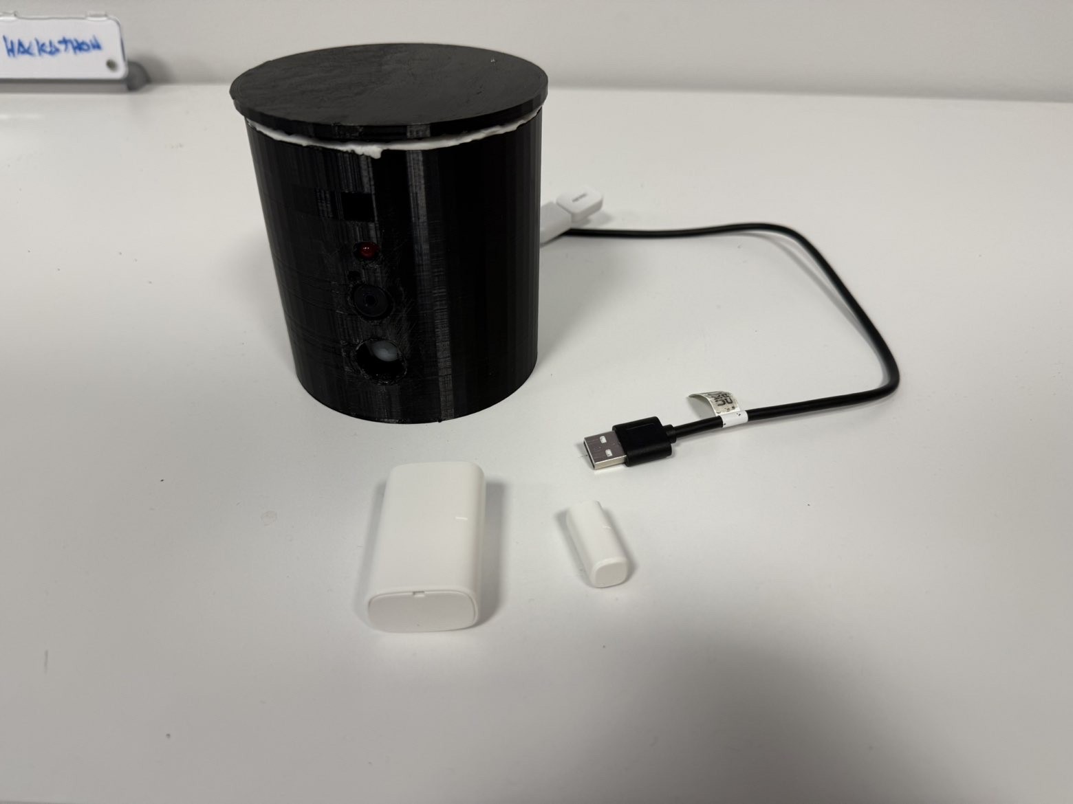
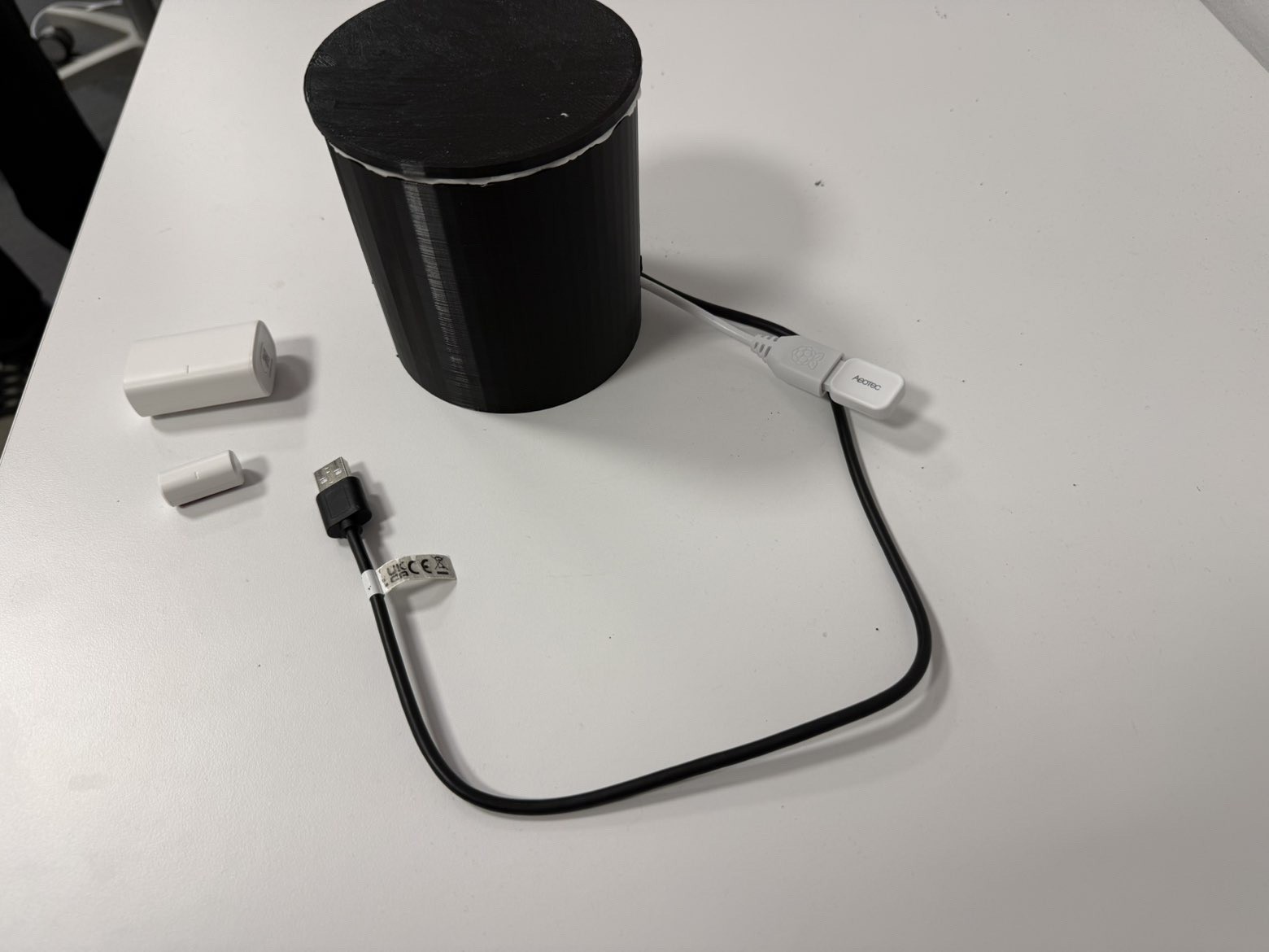
Final Product

Final assembled product

Final Product

Final Product View


Hardware Components

  • Raspberry Pi Zero WH
  • PIR sensor
  • LED
  • buzzer
  • 220 Ω resistors
  • SONOFF SNZB-04P Zigbee door/window sensor
  • Zigbee USB adapter
  • micro-USB OTG adapter
  • Raspberry Pi camera module
  • custom PCB
  • 3D-printed enclosure

System Architecture

The project is divided into the following parts:

Local Hardware

  • PIR sensor
  • LED
  • buzzer
  • Raspberry Pi GPIO connections
  • custom PCB

Wireless Sensor Layer

  • Zigbee door/window sensor
  • Zigbee USB gateway
  • Zigbee2MQTT
  • MQTT messaging

Software

  • Python backend
  • alarm logic
  • event logging
  • camera service
  • REST API

User Interface

  • React/Vite frontend
  • live system status
  • event timeline
  • control buttons
  • camera view

Deployment

  • local hosting on Raspberry Pi
  • Nginx as web server / reverse proxy

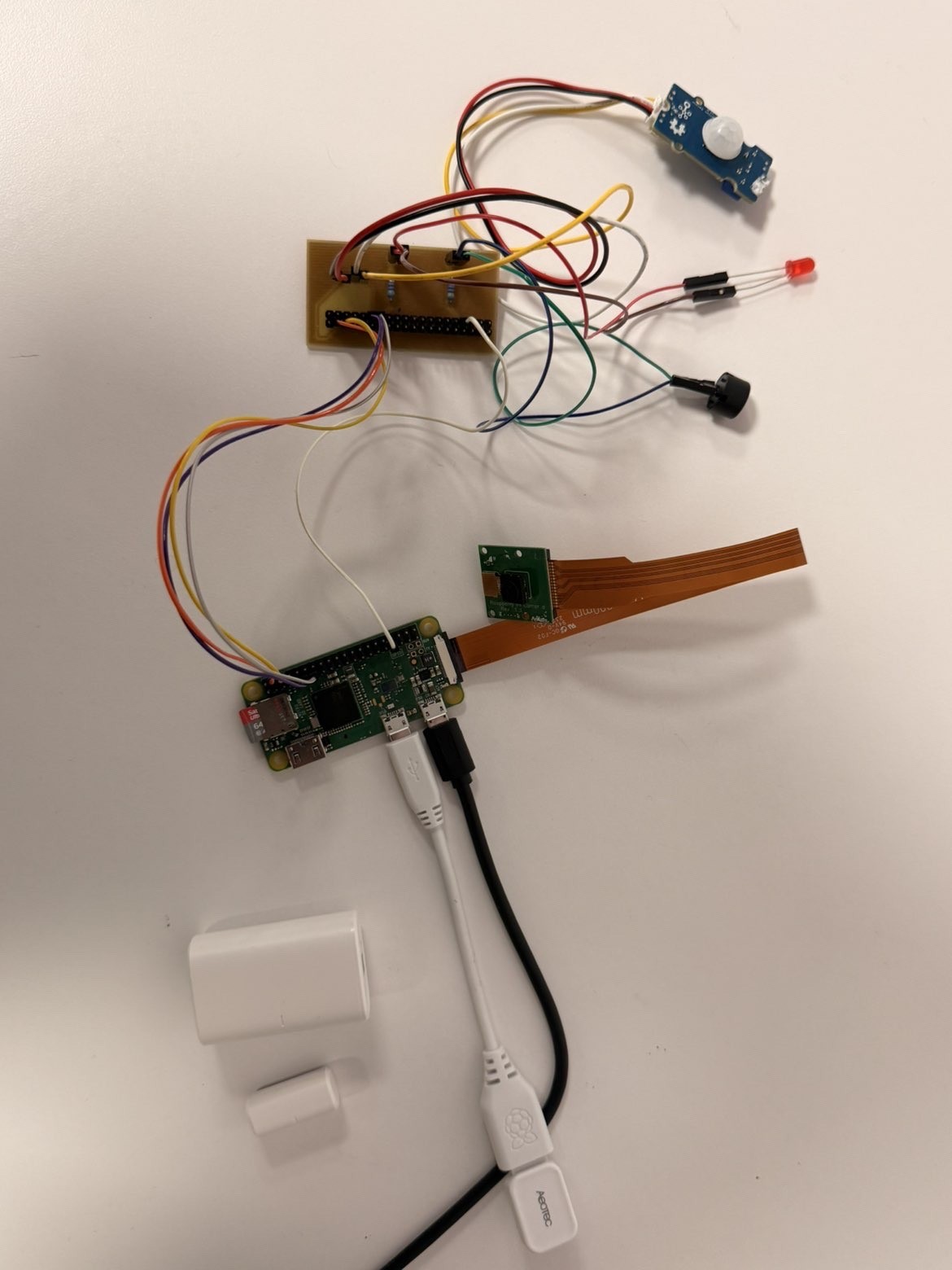
Hardware Prototype

Prototype wiring and components

Prototype

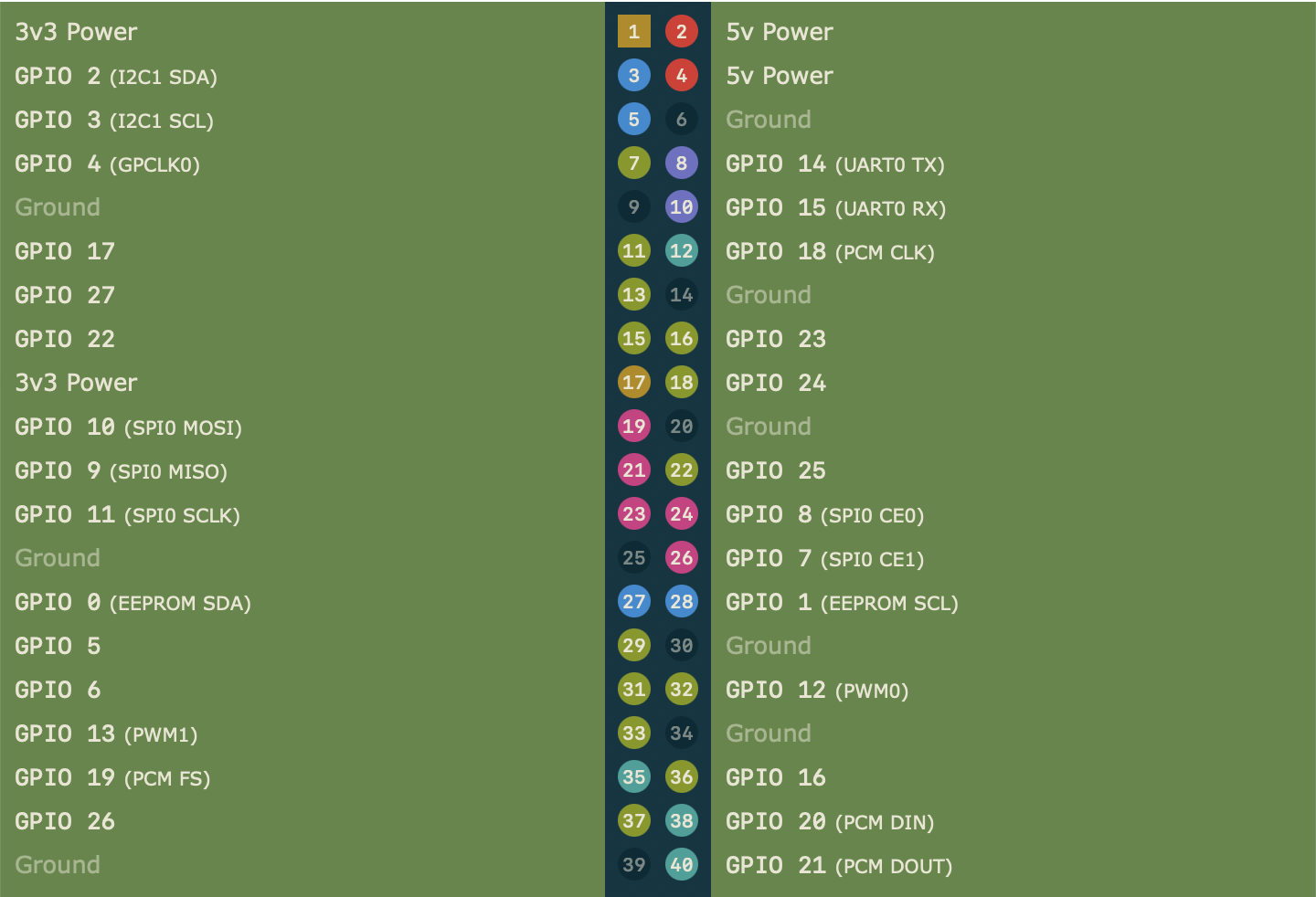
Raspberry Pi GPIO reference

GPIO Pinout


Schematic and PCB Design

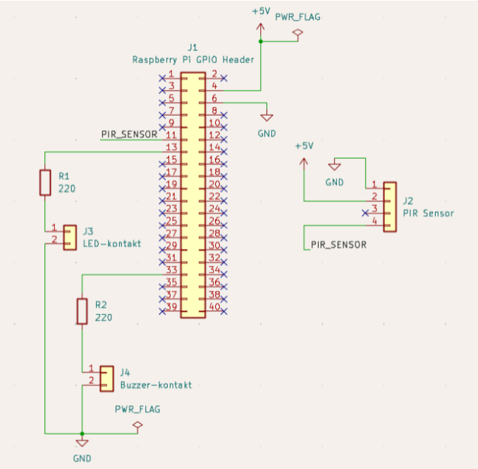
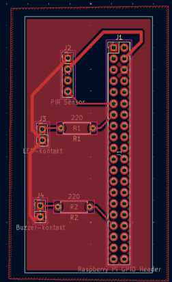
The PCB was designed in KiCad based on the local hardware part of the system.

KiCad schematic

Schematic

PCB layout

PCB Layout

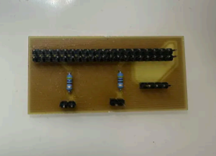
Manufactured PCB

PCB

The PCB includes the local electronics for:

  • Raspberry Pi header
  • PIR sensor connection
  • LED connection
  • buzzer connection
  • resistors

The camera and Zigbee door sensor are handled separately and are not mounted directly on the PCB.


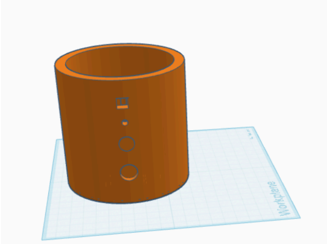
3D Enclosure Design

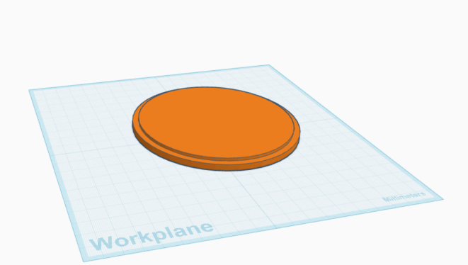
A custom enclosure was designed to make the prototype more compact and easier to demonstrate.

Enclosure lid CAD

CAD Lid

Main enclosure CAD

CAD Enclosure


How the System Works

  1. The Raspberry Pi continuously monitors the PIR sensor and listens for door sensor events.
  2. If motion is detected or the door opens while the system is armed:
    • the alarm state is triggered
    • LED and buzzer are activated
    • the event is logged
    • the web dashboard updates automatically
    • the camera can be used for visual verification
  3. The user can monitor and control the system through the local web interface.

Network Communication

The door/window sensor is not connected directly to the GPIO pins.
Instead, it communicates wirelessly over Zigbee.

The communication flow is:

Door Sensor -> Zigbee -> Zigbee USB Adapter -> Zigbee2MQTT -> MQTT -> Python Backend -> Frontend

The PIR sensor, LED, and buzzer are connected locally to the Raspberry Pi.


Web Dashboard

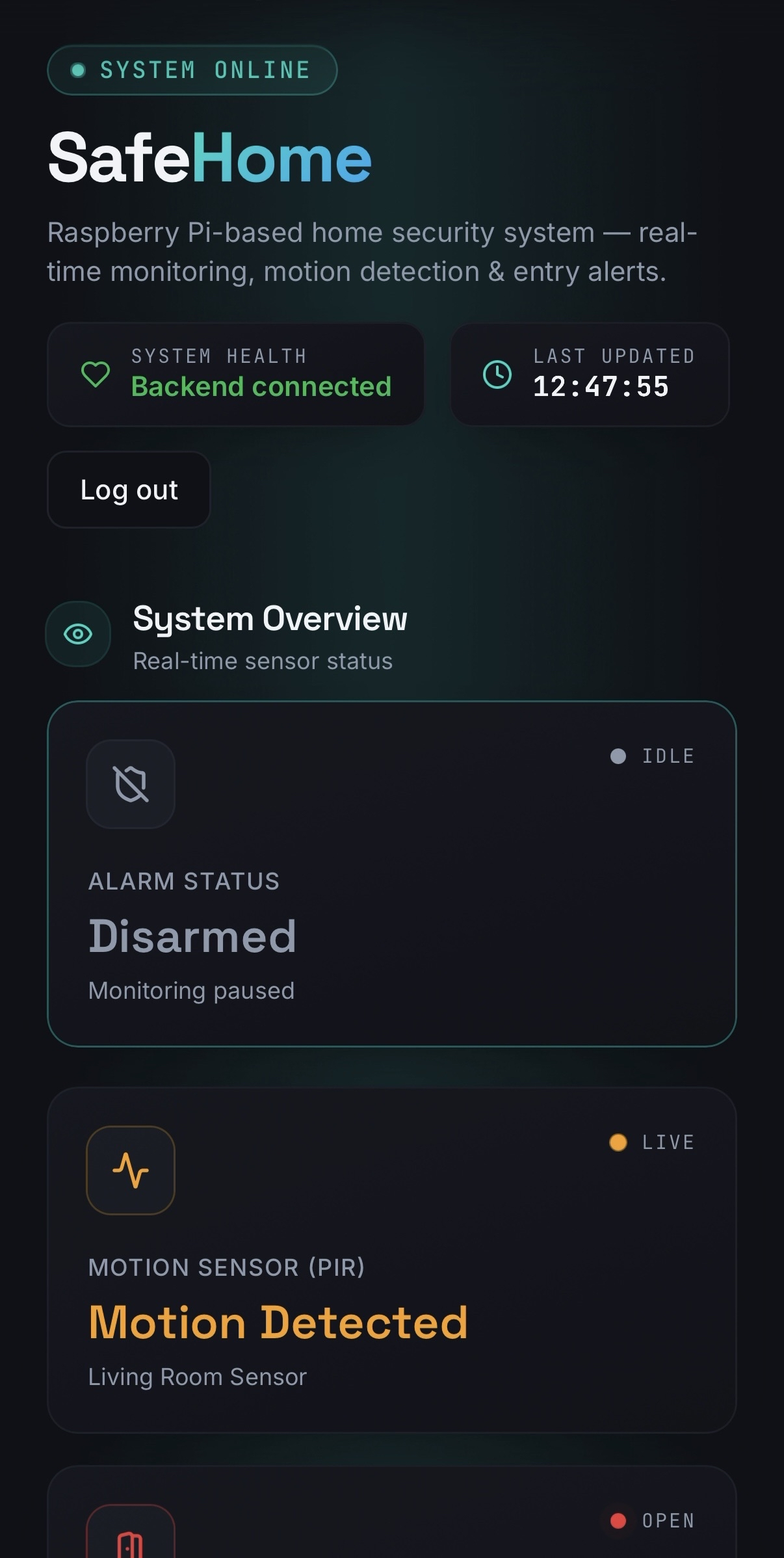
The web interface is used to monitor and control the system in real time.

It shows:

  • alarm status
  • motion status
  • door status
  • LED status
  • buzzer status
  • camera status
  • event log
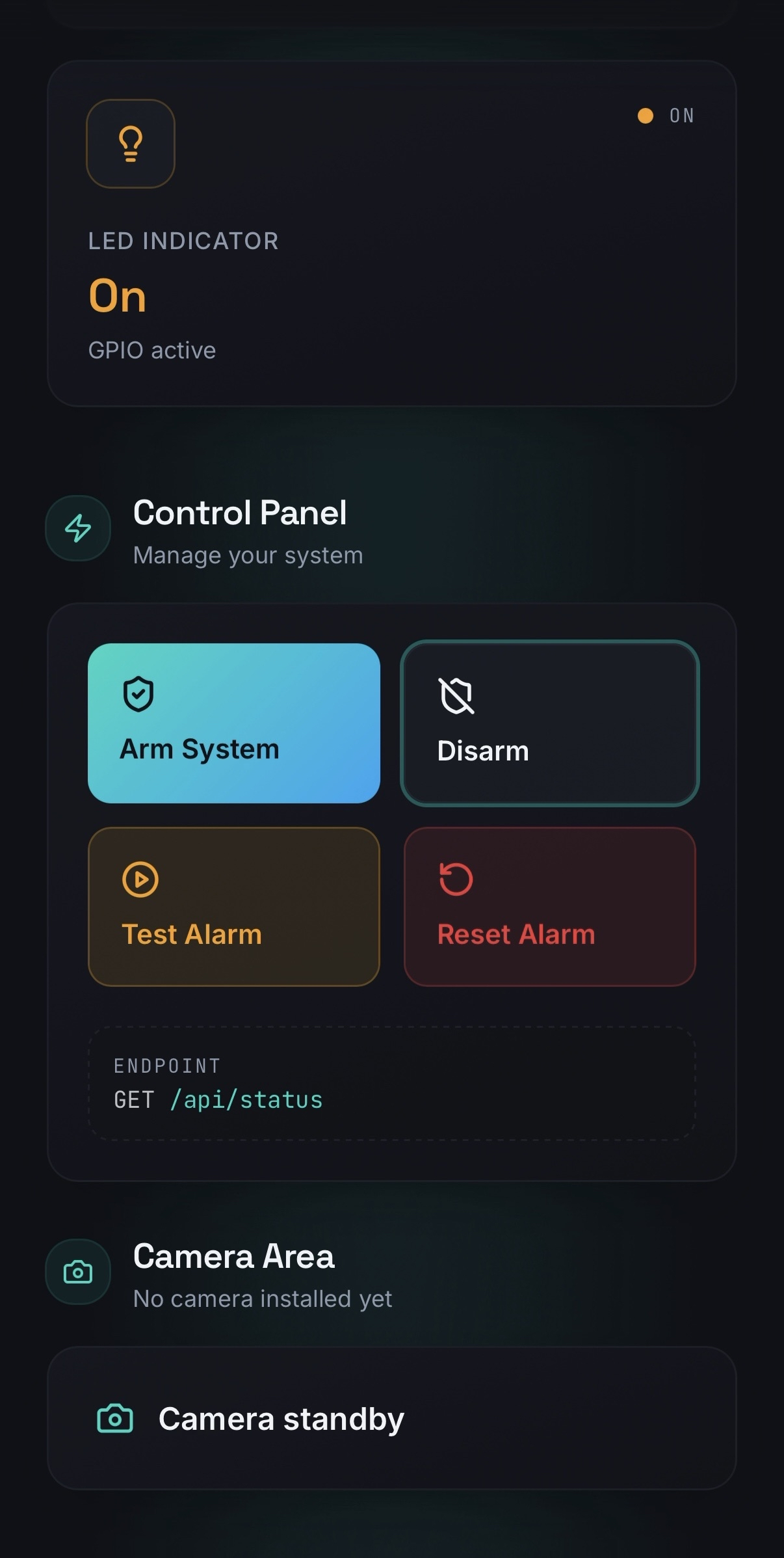
  • control buttons for arm / disarm / reset / test

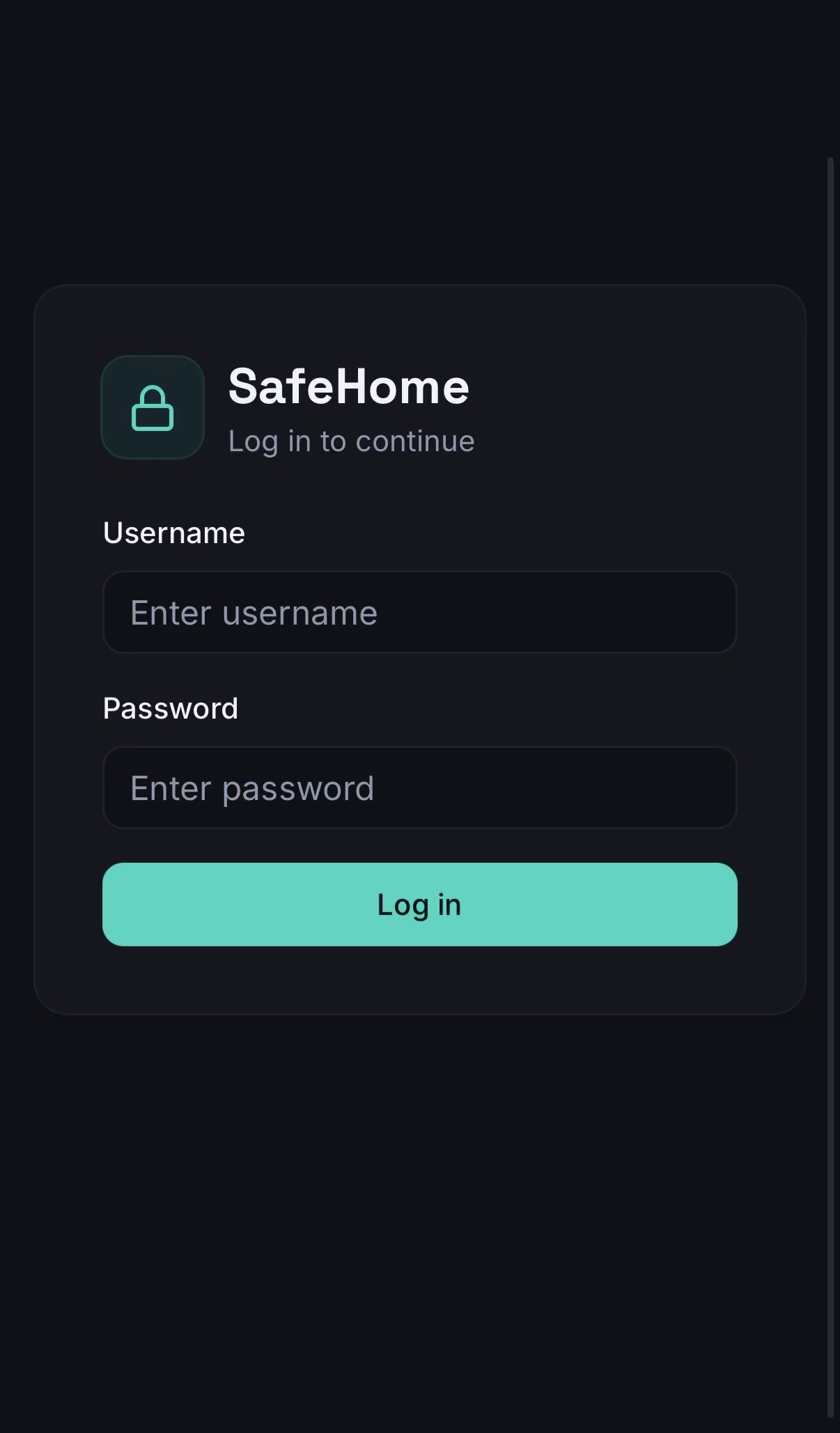
Login page

Login Page

Dashboard overview

Dashboard Overview

Control panel and standby camera area

Control Panel

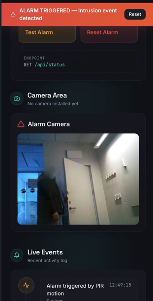
Alarm camera view

Alarm Camera

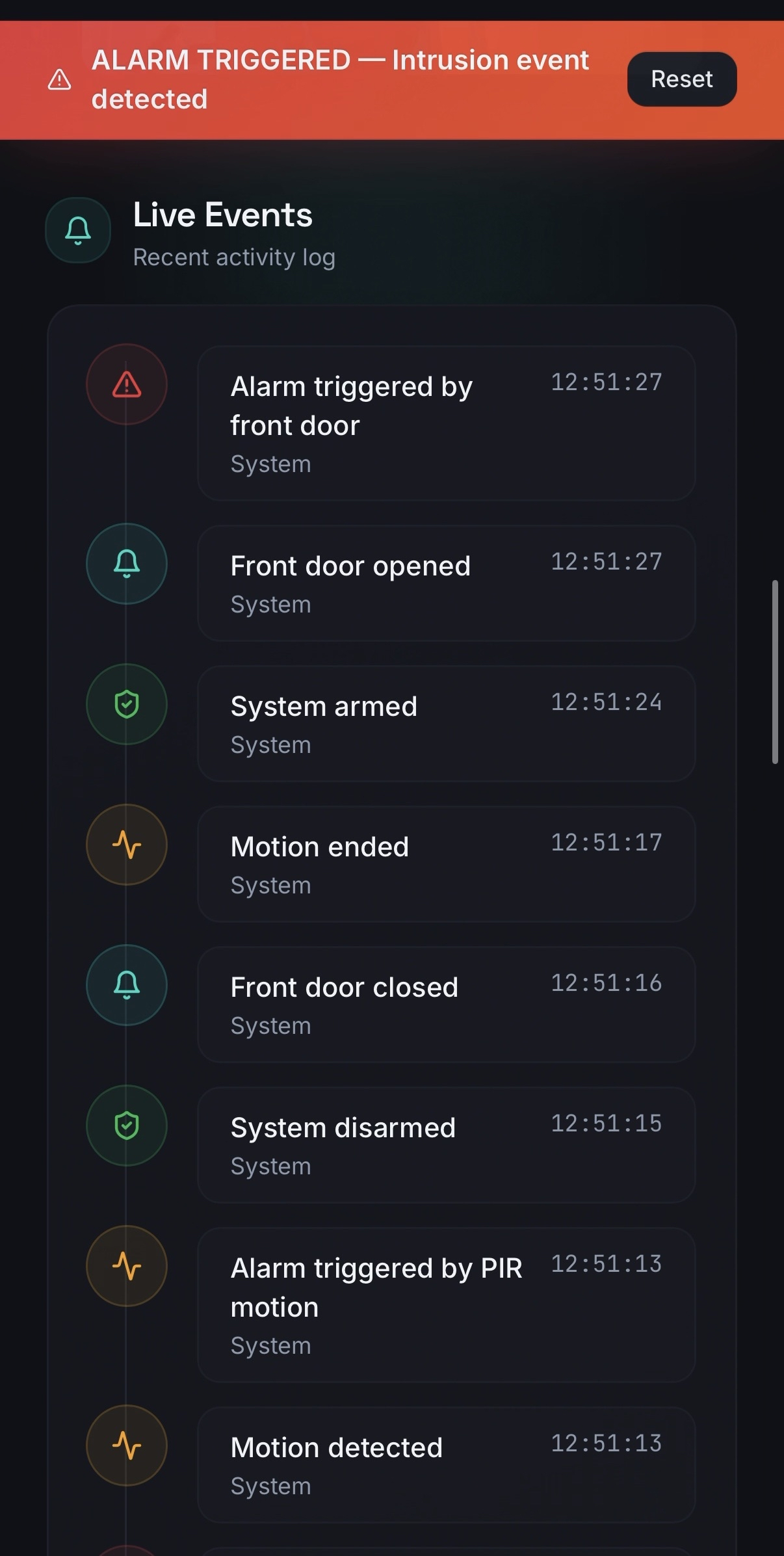
Live event log

Live Events

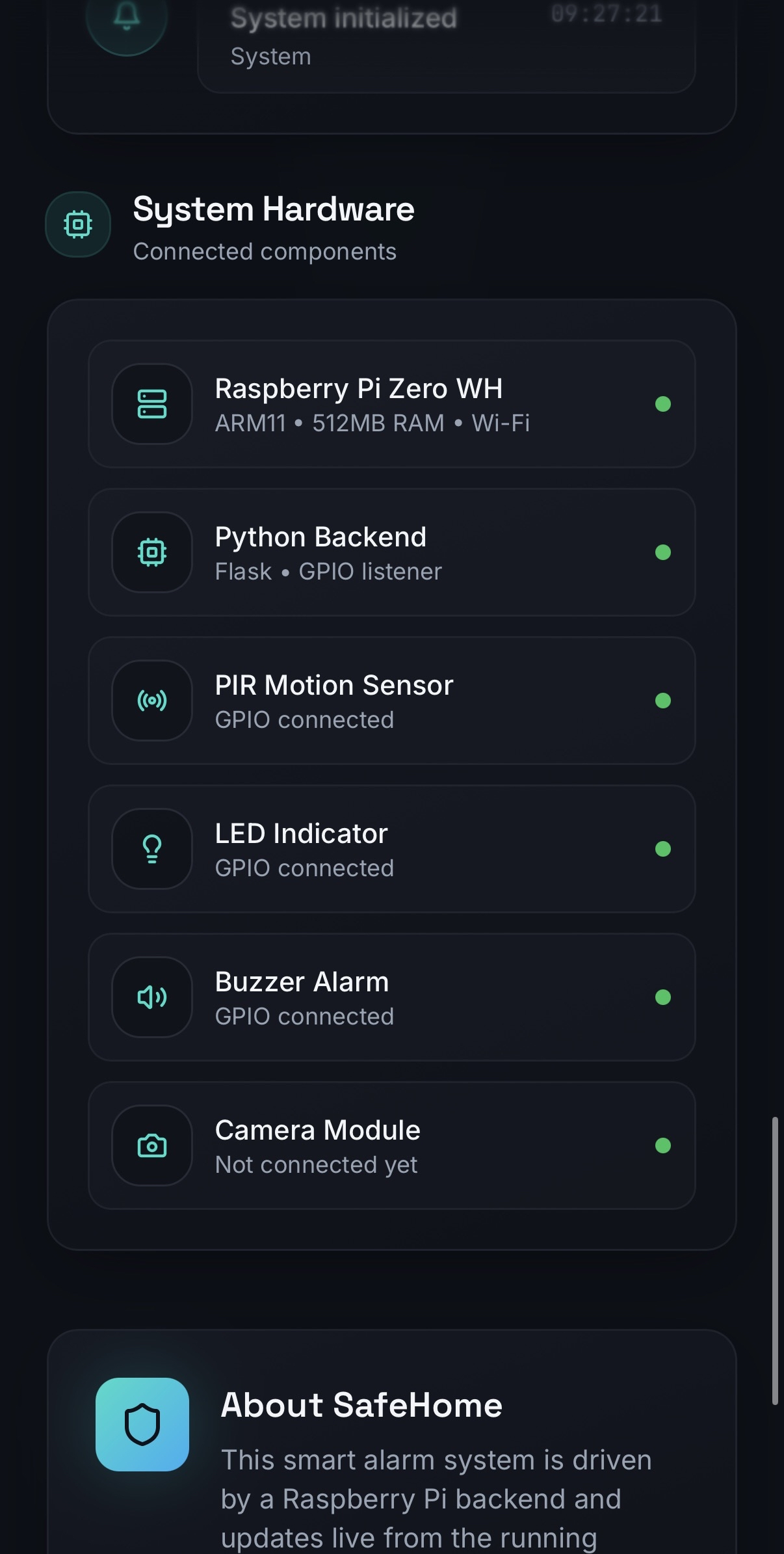
Hardware status section

Hardware Status

Parts

6
QtyValueFootprintReferences
2220Resistor_THT:R_Axial_DIN0207_L6.3mm_D2.5mm_P7.62mm_HorizontalR1, R2
1Buzzer-kontaktConnector_PinHeader_2.54mm:PinHeader_1x02_P2.54mm_VerticalJ4
1LED-kontaktConnector_PinHeader_2.54mm:PinHeader_1x02_P2.54mm_VerticalJ3
1PIR SensorConnector_PinHeader_2.54mm:PinHeader_1x04_P2.54mm_VerticalJ2
1Raspberry Pi GPIO HeaderConnector_PinHeader_2.54mm:PinHeader_2x20_P2.54mm_VerticalJ1

Similar boards

  • 2 layers18.5 × 11.1 mmSwitch, the printed circuit board in 3D

    Switch

    byrantech/laptop

    anyon_e, a highly integrated, high end, open source laptop. Attempt the impossible.

    6 parts4.3kMIT
  • 2 layers14.6 × 33 mmBrain board SD Card 1, the printed circuit board in 3D

    Brain board SD Card 1

    rusefi/rusefi

    rusefi - GPL internal combustion engine control unit

    6 parts1.2k
  • 2 layers9 × 9 mmDpoint, the printed circuit board in 3D

    Dpoint

    Jcparkyn/dpoint

    Open-source digital stylus using camera tracking and inertial measurements

    6 parts1.1kMIT
  • 2 layers51.5 × 16.6 mmMicroswitchXY Endstop, the printed circuit board in 3D

    MicroswitchXY Endstop

    VoronDesign/Voron-Hardware

    Cool Hardware designed by the Voron Design group

    6 parts1.1kGPL-3.0
  • 2 layers21.9 × 76.7 mmAmiga External, the printed circuit board in 3D

    Amiga External

    hoglet67/RGBtoHDMI

    Bare-metal Raspberry Pi project that provides pixel-perfect sampling of Retro Computer RGB/YUV video and conversion to HDMI

    6 parts1kGPL-3.0
  • 2 layers88.9 × 50.8 mmBusinesscard, the printed circuit board in 3D

    Businesscard

    hackclub/OnBoard

    💡 Join 1,000 teenagers and make your first PCB with a $100 grant!

    6 parts915
  • 2 layers20.3 × 15.2 mmL0 RGB led, the printed circuit board in 3D

    L0 RGB led

    Luos-io/luos_engine

    Open-source and real-time orchestrator for cyber-physical-systems, to easily design, test and deploy embedded applications and digital twins.

    6 parts546MIT
  • 2 layers9 × 3.6 mmOpticalEncoder, the printed circuit board in 3D

    OpticalEncoder

    adamb314/ServoProject

    Getting the most out of your hobby servo

    6 parts545

Questions

How big is the Hemlarm PCB?

It measures 30.5 × 58.5 mm and has 2 copper layers, 1.6 mm thick.

What parts does the Hemlarm use?

6 parts. The full list of its parts is on this page, with links to each part's symbol and footprint where PCBKit's library has them.

Where can I download the Hemlarm KiCad files?

From the neez11/Smart-Home-Alarm repository on GitHub, at the commit this page was made from: the board is hardware/hemlarm.kicad_pcb and its schematic hardware/hemlarm.kicad_sch. PCBKit opens the board in the browser, with nothing to install.

Can I use the Hemlarm design in my own project?

Its repository states no licence, so its author keeps all rights: ask neez11 before reusing the design.