
4 layers48 × 35 mm

 ndr-lmnc/regolo2
REGOLO an open source 10-channel USB control surface designed for software-based audio volume control.
Mobo is an open-source printed circuit board by ndr-lmnc, from the ndr-lmnc/regolo repository on GitHub, published under the CERN-OHL-S-2.0 licence. It is a 4-layer board of 100 × 79 mm with 134 parts on 109 nets, routed with 545 tracks and 263 vias.
It is built around the USBLC6-2P6. Its parts include 44 resistors, 31 capacitors, 20 diodes, 12 switches and 3 ICs. It belongs with the audio and music boards and the RISC-V boards of this library.
REGOLO is a 10-channel USB control surface designed for software-based audio volume control.
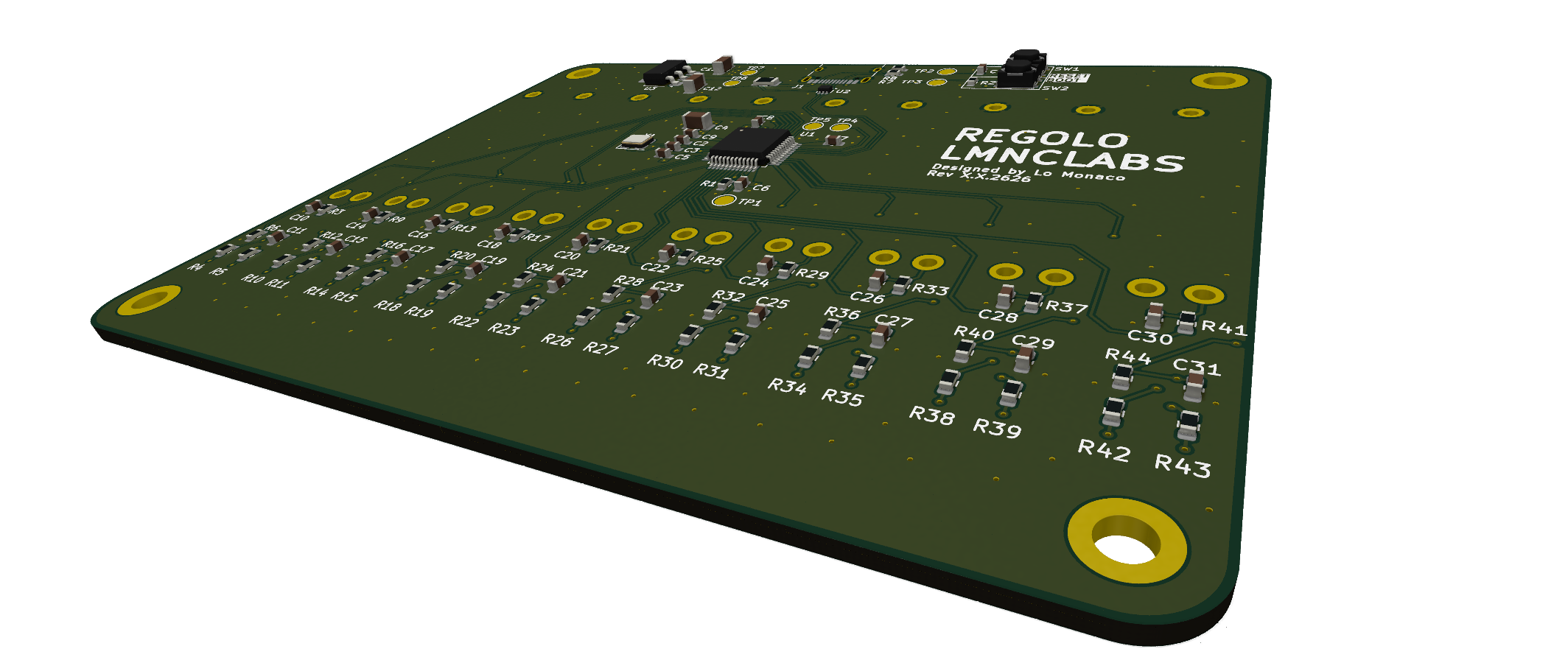
Its purpose is to provide direct physical control over system and application audio, such as:
REGOLO is not intended to be an analog audio mixer. It is a hardware controller for software-side audio mixing.
REGOLO is designed to make everyday audio routing faster and more intuitive by providing dedicated physical controls for tasks like:
A typical use case is a desktop, streaming, or studio setup where multiple audio sources coexist: system output, microphones, browser audio, media players, communication apps, and creative tools.
The intended architecture is simple:
This means the actual audio logic lives on the host computer, while REGOLO acts as a dedicated physical interface.
Based on the current repository state, the hardware is organized as follows.
Each channel is replicated as the same building block and exposes:
A_OUT: analog output from the volume controlmute: mute switch statestatus: LED control lineIn the PCB project, each channel includes:
RS301111A01G local footprint)XKB5858-Z-TP)The device is built around a WCH CH32V203, used to:
ADC_[1..10])SW_[1..10])LED_[1..10])The schematic also includes programming and debug-related signals such as:
SWDIOSWCLKRSTBOOT0BOOT1The current USB section includes:
The repository currently focuses on the hardware design of the device.
pcb/mobo/pcb/components/firmware/ is currently empty)regolo/
├── firmware/ # Device firmware (to be developed)
├── pcb/
│ ├── components/ # Local KiCad symbols and footprints
│ └── mobo/ # Main board project
│ ├── mobo.kicad_pro
│ ├── mobo.kicad_sch
│ ├── mobo.kicad_pcb
│ ├── channel.kicad_sch
│ ├── mcu.kicad_sch
│ └── usb.kicad_sch
├── LICENSE
└── README.mdTo inspect or modify the PCB design:
pcb/mobo/mobo.kicad_proThe project uses local libraries stored in:
pcb/components/The firmware is planned around WCH Fun.
WCH Fun is a lightweight framework well suited for WCH microcontrollers and fits the goals of the project:
The firmware side is expected to handle:
Example 10-channel assignments:
The channel mapping is expected to be software-configurable.
As the current design suggests, REGOLO is a control surface, not a board that directly processes analog audio signals. Volume control is performed in software, with the operating system or a host application responsible for managing the actual audio levels.
REGOLO uses a split licensing model that matches the different nature of its hardware and software sources.
The hardware design files are licensed under the CERN Open Hardware Licence Version 2 - Strongly Reciprocal (CERN-OHL-S-2.0).
This applies to the open hardware sources in the repository, including for example:
The full hardware license text is available in LICENSE.
The firmware in firmware/ is licensed under the MIT License.
The firmware license text is available in firmware/LICENSE.
This gives the embedded software side a simple and widely used open source license, while keeping the hardware design under a proper open hardware license.
Unless otherwise noted:
CERN-OHL-S-2.0MITIf host-side software is added to the repository in the future, it may follow the same MIT license or be licensed separately where appropriate.
| Qty | Value | Footprint | References |
|---|---|---|---|
| 26 | 100n | Capacitor_SMD:C_0603_1608Metric | C1, C10, C11, C14, C15, C16, C17, C18, C19, C20, C21, C22, C23, C24, C25, C26 +10 |
| 12 | 10k | Resistor_SMD:R_0603_1608Metric | R1, R2, R6, R12, R16, R20, R24, R28, R32, R36, R40, R44 |
| 10 | 1k | Resistor_SMD:R_0603_1608Metric | R3, R9, R13, R17, R21, R25, R29, R33, R37, R41 |
| 10 | 1k5 | Resistor_SMD:R_0603_1608Metric | R5, R11, R15, R19, R23, R27, R31, R35, R39, R43 |
| 10 | 470 | Resistor_SMD:R_0603_1608Metric | R4, R10, R14, R18, R22, R26, R30, R34, R38, R42 |
| 10 | AMBER | LED_SMD:LED_0805_2012Metric | D2, D4, D6, D8, D10, D12, D14, D16, D18, D20 |
| 10 | R_Potentiometer | local:RS301111A01G | RV1, RV2, RV3, RV4, RV5, RV6, RV7, RV8, RV9, RV10 |
| 10 | SW_DPDT_x2 | local:XKB5858-Z-TP | SW3, SW4, SW5, SW6, SW7, SW8, SW9, SW10, SW11, SW12 |
| 10 | WHITE | LED_SMD:LED_0805_2012Metric | D1, D3, D5, D7, D9, D11, D13, D15, D17, D19 |
| 7 | TestPoint | TestPoint:TestPoint_Pad_D2.0mm | TP1, TP2, TP3, TP4, TP5, TP6, TP7 |
| 4 | MountingHole | MountingHole:MountingHole_3.2mm_M3_ISO14580_Pad_TopBottom | H1, H2, H3, H4 |
| 2 | 22p | Capacitor_SMD:C_0603_1608Metric | C2, C3 |
| 2 | 5k1 | Resistor_SMD:R_0603_1608Metric | R7, R8 |
| 2 | SW_SPST | Button_Switch_SMD:SW_SPST_PTS810 | SW1, SW2 |
| 1 | 10u | Capacitor_SMD:C_1206_3216Metric | C12 |
| 1 | 1u | Capacitor_SMD:C_1206_3216Metric | C4 |
| 1 | 22u | Capacitor_SMD:C_1206_3216Metric | C13 |
| 1 | AZ1117CH2-3.3 | Package_TO_SOT_SMD:SOT-223-3_TabPin2 | U3 |
| 1 | CH32V203CxTx | Package_QFP:LQFP-48_7x7mm_P0.5mm | U1 |
| 1 | Crystal_GND24_Small | Crystal:Crystal_SMD_3225-4Pin_3.2x2.5mm | Y1 |
| 1 | Polyfuse | Fuse:Fuse_1206_3216Metric | F1 |
| 1 | USBLC6-2P6 | Package_TO_SOT_SMD:SOT-666 | U2 |
| 1 | USB_C_Receptacle_USB2.0_16P | Connector_USB:USB_C_Receptacle_HRO_TYPE-C-31-M-12 | J1 |

Bastardkb/Dilemma
The Dilemma is a vertical stagger low-profile keyboard with mods.


Twisted-Fields/rp2040-motor-controller
A dual channel brushless motor controller based on the RP2040 microcontroller, designed in Kicad.


ZSWatch/Watch-DevKit-HW
The hardware repo for the ZSWatch Development Kit.
It measures 100 × 79 mm and has 4 copper layers, 1.6 mm thick.
134 parts, built around the USBLC6-2P6. The full list of its parts is on this page, with links to each part's symbol and footprint where PCBKit's library has them.
From the ndr-lmnc/regolo repository on GitHub, at the commit this page was made from: the board is pcb/mobo/mobo.kicad_pcb and its schematic pcb/mobo/channel.kicad_sch. PCBKit opens the board in the browser, with nothing to install.
Its repository publishes it under the CERN-OHL-S-2.0 licence: you may reuse it on that licence's terms (keep the author's notice, and for a copyleft licence share your changes alike).