2 layers51.7 × 79.4 mm
Control motor dc
kr4fty/DCMotorController
Closed Loop Position Control for DC Servo Motors. STEP / DIR compatible Driver
26 parts5GPL-2.0

 ndhuy1127/DA2-KIT-ATmega16
Đồ án 2 HUST 20261 - DA26111: Thiết kế và phát triển KIT ATmega16
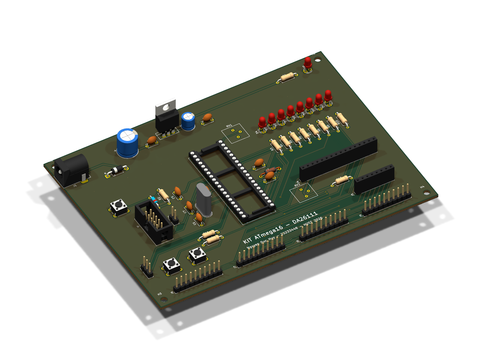
KIT ATmega16 is an open-source printed circuit board by ndhuy1127, from the ndhuy1127/DA2-KIT-ATmega16 repository on GitHub. It is a 2-layer board of 150 × 110 mm with 57 parts on 58 nets, routed with 598 tracks and 22 vias.
It is built around the ATMEGA16A-PU, LM7805 and 100UF/16V. Its parts include 13 resistors, 11 diodes, 10 capacitors, 9 connectors and 3 switches. It belongs with the AVR (ATmega, ATtiny) boards of this library.


Đồ án 2 – Học kỳ 20261 – Đại học Bách khoa Hà Nội
Đề tài thiết kế và lập trình một bo KIT dùng ATmega16. Trên bo có khối nguồn 5 V, thạch anh 8 MHz, cổng nạp ISP cho USBasp, 8 LED đơn, 2 nút nhấn nối vào ngắt ngoài, biến trở để thử ADC, cổng UART, chỗ cắm LCD1602 và bàn phím 4×4, cùng 4 header để đưa các cổng PORTA–PORTD ra ngoài.
| Tuần | Nội dung | Tài liệu | Trạng thái |
|---|---|---|---|
| 1 | Tìm hiểu yêu cầu, datasheet, sơ đồ khối | tuan-01 | Xong |
| 2 | Phân chân, chọn linh kiện, BOM | pinmap, BOM | Xong |
| 3 | Vẽ schematic, ERC | tuan-03, PDF | Xong |
| 4 | Vẽ PCB, DRC, xuất Gerber | tuan-04, Gerber | Xong |
| 5 | Mô phỏng GPIO, nút nhấn, ngắt ngoài, Timer | tuan-05, firmware | Đang làm |
| 6 | Mô phỏng ADC, UART | ||
| 7 | Mô phỏng LCD1602, bàn phím 4×4 | ||
| 8 | Bài tổng hợp, hàn lắp bo | ||
| 9 | Chạy trên bo thật, đo kiểm | ||
| 10 | Báo cáo, slide, demo |
Lịch chi tiết xem ở docs/ke-hoach/ke-hoach-dieu-chinh.md.
docs/          kế hoạch, phiếu báo cáo tuần, tài liệu từng tuần
hardware/      project KiCad, file xuất (PDF, Gerber, BOM, ảnh 3D) và script hỗ trợ
firmware/      mã nguồn các bài lab, board.h chứa phân chân dùng chung
simulation/ mạch mô phỏng ProteusTrên Windows cài avr-gcc bằng Scoop (scoop install avr-gcc), sau đó:
cd firmware
powershell -ExecutionPolicy Bypass -File build.ps1                       # build hết, ra build/*.hex
powershell -ExecutionPolicy Bypass -File build.ps1 -Lab 04_timer -Flash  # build và nạp 1 bài qua USBasp
Với chip mới cần ghi fuse một lần để chạy thạch anh 8 MHz và tắt JTAG:
avrdude -c usbasp -p m16 -U lfuse:w:0xFF:m -U hfuse:w:0xD9:mMở hardware/kicad/KIT-ATmega16.kicad_pro bằng KiCad 10. Schematic chạy ERC không còn lỗi;
PCB chạy DRC không còn lỗi và khớp với schematic, chỉ còn vài cảnh báo chữ silkscreen bị chồng.
| Qty | Value | Footprint | References |
|---|---|---|---|
| 8 | 330 | Resistor_THT:R_Axial_DIN0207_L6.3mm_D2.5mm_P10.16mm_Horizontal | R3, R4, R5, R6, R7, R8, R9, R10 |
| 8 | Đỏ | LED_THT:LED_D3.0mm | D4, D5, D6, D7, D8, D9, D10, D11 |
| 6 | 100nF | Capacitor_THT:C_Disc_D5.0mm_W2.5mm_P5.00mm | C2, C4, C5, C8, C9, C10 |
| 4 | M3 | MountingHole:MountingHole_3.2mm_M3 | H1, H2, H3, H4 |
| 3 | 10k | Resistor_THT:R_Axial_DIN0207_L6.3mm_D2.5mm_P10.16mm_Horizontal | R2, R11, R12 |
| 2 | 10k | Potentiometer_THT:Potentiometer_Bourns_3386P_Vertical | RV1, RV2 |
| 2 | 22pF | Capacitor_THT:C_Disc_D5.0mm_W2.5mm_P5.00mm | C6, C7 |
| 1 | 100uF/16V | Capacitor_THT:CP_Radial_D6.3mm_P2.50mm | C3 |
| 1 | 10uH | Inductor_THT:L_Axial_L5.3mm_D2.2mm_P10.16mm_Horizontal_Vishay_IM-1 | L1 |
| 1 | 1N4007 | Diode_THT:D_DO-41_SOD81_P10.16mm_Horizontal | D1 |
| 1 | 1N4148 | Diode_THT:D_DO-35_SOD27_P7.62mm_Horizontal | D3 |
| 1 | 1k | Resistor_THT:R_Axial_DIN0207_L6.3mm_D2.5mm_P10.16mm_Horizontal | R1 |
| 1 | 33 | Resistor_THT:R_Axial_DIN0207_L6.3mm_D2.5mm_P10.16mm_Horizontal | R13 |
| 1 | 470uF/25V | Capacitor_THT:CP_Radial_D10.0mm_P5.00mm | C1 |
| 1 | 8MHz | Crystal:Crystal_HC49-U_Vertical | Y1 |
| 1 | ATmega16A-PU | Package_DIP:DIP-40_W15.24mm_Socket | U1 |
| 1 | Cấp 5V từ ISP | Connector_PinHeader_2.54mm:PinHeader_1x02_P2.54mm_Vertical | JP1 |
| 1 | DC 9-12V | Connector_BarrelJack:BarrelJack_Horizontal | J1 |
| 1 | ISP (USBasp) | Connector_IDC:IDC-Header_2x05_P2.54mm_Vertical | J2 |
| 1 | Keypad 4x4 | Connector_PinSocket_2.54mm:PinSocket_1x08_P2.54mm_Vertical | J5 |
| 1 | LCD1602 | Connector_PinSocket_2.54mm:PinSocket_1x16_P2.54mm_Vertical | J4 |
| 1 | LM7805 | Package_TO_SOT_THT:TO-220-3_Vertical | U2 |
| 1 | PORTA | Connector_PinHeader_2.54mm:PinHeader_1x10_P2.54mm_Vertical | J6 |
| 1 | PORTB | Connector_PinHeader_2.54mm:PinHeader_1x10_P2.54mm_Vertical | J7 |
| 1 | PORTC | Connector_PinHeader_2.54mm:PinHeader_1x10_P2.54mm_Vertical | J8 |
| 1 | PORTD | Connector_PinHeader_2.54mm:PinHeader_1x10_P2.54mm_Vertical | J9 |
| 1 | RESET | Button_Switch_THT:SW_PUSH_6mm | SW3 |
| 1 | SW1 (INT0) | Button_Switch_THT:SW_PUSH_6mm | SW1 |
| 1 | SW2 (INT1) | Button_Switch_THT:SW_PUSH_6mm | SW2 |
| 1 | USB-UART | Connector_PinHeader_2.54mm:PinHeader_1x03_P2.54mm_Vertical | J3 |
| 1 | Xanh | LED_THT:LED_D3.0mm | D2 |
kr4fty/DCMotorController
Closed Loop Position Control for DC Servo Motors. STEP / DIR compatible Driver

davixcky/entrenador-atmega328p
Entrenador de microcontroladores con ATMega328P (DIP) - Sistemas Embebidos 1, actividad 10.1.12


MartinFeichtinger/kneippometer
This is a project to build an self-sufficient temperatur display for the local kneipp bath

Zinjpq/Egg_incubator_project
Major exercise of pulse engineering subject
It measures 150 × 110 mm and has 2 copper layers, 1.6 mm thick.
57 parts, built around the ATMEGA16A-PU, LM7805 and 100UF/16V. The full list of its parts is on this page, with links to each part's symbol and footprint where PCBKit's library has them.
From the ndhuy1127/DA2-KIT-ATmega16 repository on GitHub, at the commit this page was made from: the board is hardware/kicad/KIT-ATmega16.kicad_pcb and its schematic hardware/kicad/KIT-ATmega16.kicad_sch. PCBKit opens the board in the browser, with nothing to install.
Its repository states no licence, so its author keeps all rights: ask ndhuy1127 before reusing the design.