4 layers55 × 55 mm

 Ndambia/lilygo
A custom 4-layer KiCad PCB design integrating an ESP32 Wi-Fi/Bluetooth microcontroller with a SIM7600G-H 4G LTE Cat-4 cellular module, comprehensive power management, GPS tracking, GPRS connectivity, USB-C charging…
Lilygo is an open-source printed circuit board by Ndambia, from the Ndambia/lilygo repository on GitHub. It is a 4-layer board of 77.9 × 81.6 mm with 188 parts on 203 nets, routed with 1,190 tracks and 388 vias.
It is built around the ESP32-WROOM-32, SIM7600G-H R2 and MT3608, with the AM2302, AS312 and RS0108YQ20 among its other parts. Its parts include 69 capacitors, 57 resistors, 19 diodes, 10 ICs and 8 inductors. It belongs with the radio and wireless boards and the ESP32 boards of this library.


A custom 4-layer KiCad PCB design integrating an ESP32 Wi-Fi/Bluetooth microcontroller with a SIM7600G-H 4G LTE Cat-4 cellular module, comprehensive power management, GPS tracking, GPRS connectivity, USB-C charging, LiPo battery management, environmental sensing, and USB-to-UART programming support.
This project is a compact, feature-rich IoT development board built around the ESP32-WROOM-32 and the SIM7600G-H R2 4G LTE module. It is designed for applications requiring cellular connectivity (4G/GPRS), GPS positioning, local Wi-Fi/Bluetooth, environmental sensing, and flexible power management from USB-C or a LiPo battery.
The board is designed in KiCad and targets JLCPCB / LCSC manufacturing and assembly (full BOM with LCSC part numbers included).
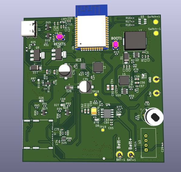
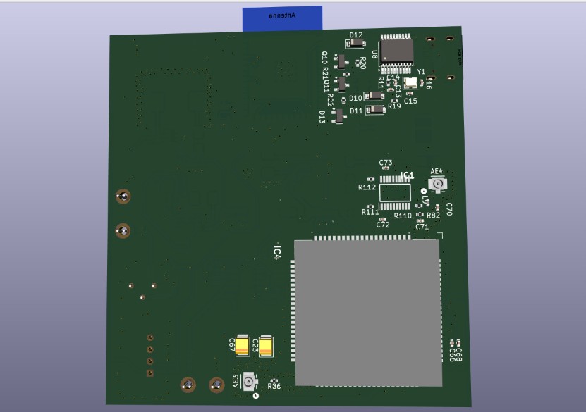
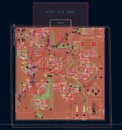
The full schematic (all sheets combined) is available as:
PCB info/schematic.pdf — Full combined schematic (all sheets)Individual sheet PDFs:
| Sheet | Description | |
|---|---|---|
| Root | Top-level schematic, ESP32, USB-UART, interfaces | (see full schematic) |
| BUCK_CONVERTER_3V3_2A | 3.3 V / 2 A step-down (TPS56339DDCR) | schematic-BUCK_CONVERTER_3V3_2A_TPS56339DDCR.pdf |
| LIPO_BAT_CHARGER_TP4056 | LiPo charger and protection circuit | schematic-LIPO_BAT_CHARGER_TP4056.pdf |
| MT3608_5V_BOOST_CONVERTOR | 5 V boost converter (MT3608) | schematic-MT3608_5V_BOOST_CONVERTOR.pdf |
| POWER_PATH_SELECTOR | Automatic USB/Battery power path switching | schematic-POWER_PATH_SELECTOR.pdf |
| SIM808_GPRS_GPS_MODULE | SIM7600G-H R2 4G/GPS module and support circuitry | schematic-SIM808_GPRS_GPS_MODULE.pdf |
| Feature | Details |
|---|---|
| MCU | ESP32-WROOM-32D (Wi-Fi 802.11 b/g/n + Bluetooth 4.2 / BLE) |
| Cellular | SIM7600G-H R2 — 4G LTE Cat-4 / 3G / 2G, global bands |
| GPS / GNSS | Integrated via SIM7600G-H R2 (GPS + GLONASS) |
| USB Interface | USB-C receptacle (GCT USB4105), USB 2.0 |
| USB-to-UART | CH340T (SSOP-20) for ESP32 programming |
| LiPo Charging | TP4056 — up to 1 A charge rate, with protection |
| 3.3 V Rail | TPS56339DDCR buck converter, 2 A output |
| 5 V Boost | MT3608 step-up converter for 5 V peripherals |
| Buck-Boost | TPS630250RNCR — efficient intermediate rail |
| Power Path | Automatic USB / battery selector (NCE6005AR P-FETs) |
| Environmental Sensor | AM2302 (DHT22) — Temperature & Humidity |
| PIR Sensor | AS312 passive infrared motion detector |
| SIM Card Slot | GCT SIM7155-6-1-14-A nano/micro SIM connector |
| GPS Antenna | U.FL / IPEX connector (GT-RF1125A-01G) |
| GPRS Antenna | U.FL / IPEX connector (GT-RF1125A-01G) |
| Level Shifting | RS0108YQ20 8-channel bidirectional level shifter |
| ESD Protection | SP0502BAHT (USB lines), ESD0504F (multi-line) |
| Reset / Boot | Dedicated tactile push buttons (SKRPACE010) |
| Status LEDs | Power, Charging, Network status, RGB indicator |
| Crystal | 12 MHz SMD crystal (Y1) for CH340T |
| PCB Layers | 4-layer stackup (F.Cu / In1.Cu / In2.Cu / B.Cu) |
| Board outline | Edge cuts defined; antenna keep-out zone present |
                          ┌──────────────────────────────────────────┐
                          │              USB-C (J3)                  │
                          │         GCT USB4105-GF-A                 │
                          └───────────────┬──────────────────────────┘
                                          │ VBUS (5V)
                          ┌───────────────▼──────────────────────────┐
                          │       Power Path Selector                │
                          │  NCE6005AR P-FET switches (Q8, Q9)       │
                          │  Auto USB / LiPo selection               │
                          └────────┬──────────────┬──────────────────┘
                                   │              │
                    ┌──────────────▼──┐    ┌──────▼──────────────────┐
                    │  TP4056 LiPo    │    │   MT3608 Boost (U2)     │
                    │  Charger (U4)   │    │   VBAT → 5 V            │
                    └──────────────┬──┘    └──────┬──────────────────┘
                                   │ VBAT         │ 5V rail
                    ┌──────────────▼──────────────▼──────────────────┐
                    │           TPS56339DDCR Buck (U10)              │
                    │              → 3.3 V / 2 A                     │
                    └──────────────┬──────────────────────────────────┘
                                   │ 3.3 V
                    ┌──────────────▼──────────────────────────────────┐
                    │         ESP32-WROOM-32D (U6)                   │
│ Wi-Fi / BLE / GPIO / UART / SPI / I2C │The schematic is organized into hierarchical sheets:
Top-level sheet containing:
Full BOM:
Manufacturing files/BOM.csv
Schematic netlist CSV:schematic.csv
| Ref | Part | Description |
|---|---|---|
| U6 | ESP32-WROOM-32D-N4 | Wi-Fi + BT MCU module |
| IC4 | SIM7600G-H R2 | 4G LTE / GPS module |
| U4 | TP4056 | LiPo battery charger |
| U10 | TPS56339DDCR | 3.3 V / 2 A buck regulator |
| U2 | MT3608 | 5 V boost converter |
| IC3 | TPS630250RNCR | Buck-boost regulator |
| IC1 | RS0108YQ20 | 8-ch bidirectional level shifter |
| IC2 | AS312 | PIR motion sensor |
| U8 | CH340T (SSOP-20) | USB-to-UART bridge |
| U3 | AM2302 | DHT22 temperature & humidity sensor |
| Ref | Part | Description |
|---|---|---|
| J3 | USB4105-GF-A | USB-C receptacle (USB 2.0) |
| J1 | SIM7155-6-1-14-A | SIM card connector |
| AE3 | GT-RF1125A-01G | GPRS / LTE antenna (U.FL) |
| AE4 | GT-RF1125A-01G | GPS antenna (U.FL) |
| Ref | Value/Part | Description |
|---|---|---|
| Q8, Q9 | NCE6005AR | P-channel power MOSFETs (power path) |
| Q15, Q16 | SI2302 | N-channel MOSFETs |
| Q10, Q11 | MMBT3904 | NPN signal transistors |
| Q1 | BC817 | NPN transistor |
| D1, D17 | SS54 | 5 A Schottky diodes |
| D10–D12 | B5819W | 1 A Schottky diodes |
| D13 | BAT54C | Dual Schottky (SOT-23) |
| D28 | BZT52C4V3 | 4.3 V Zener clamp |
| D3 | SMLVN6RGBFU1 | RGB LED |
| D15, D16 | SP0502BAHT | USB ESD protection |
| D25 | ESD0504F | Multi-line ESD protection |
| Y1 | 12 MHz | SMD crystal (2520 4-pin) for CH340T |
| L1 | 22 µH | Chilisin power inductor (buck) |
| L2 | 1 µH | Chilisin power inductor (boost) |
| L5 | 4.7 µH | Chilisin power inductor (buck-boost) |
| C31, C35 | 220 µF | Electrolytic bulk caps |
| C23, C67 | 220 µF | Tantalum bulk caps (cellular surge) |
Total unique component lines in BOM: ~82 line items
USB-C VBUS (5 V)
     │
     ├──► Power Path Selector (NCE6005AR)
     │         │
     │    ┌────┴──────────────────────────────────────────┐
     │    │ When USB present: powers system, charges LiPo │
     │    │ When no USB: LiPo powers system               │
     │    └────────────────────────────────────────────────┘
     │
     ├──► TP4056 LiPo Charger ──► LiPo Battery (BAT+ / BAT-)
     │
     └──► MT3608 Boost ──► 5 V internal rail
               │
               └──► TPS56339DDCR Buck ──► 3.3 V (ESP32, logic, peripherals)
                         │
└──► TPS630250RNCR Buck-Boost ──► SIM7600G-H power rail| Rail | Regulator | Max Current | Load |
|---|---|---|---|
| 5 V boost | MT3608 | 2 A | Module VCC, USB |
| 3.3 V | TPS56339DDCR | 2 A | ESP32, logic ICs, sensors |
| Module VCC | TPS630250RNCR | — | SIM7600G-H R2 |
| VBAT | TP4056 output | 1 A charge | LiPo cell |
| Interface | Notes |
|---|---|
| 4G LTE / GPRS | SIM7600G-H R2, global bands, SMA/U.FL antenna |
| GPS / GNSS | Integrated in SIM7600G-H R2, dedicated U.FL antenna |
| Wi-Fi | ESP32 802.11 b/g/n (PCB trace antenna on module) |
| Bluetooth | ESP32 BT Classic 4.2 + BLE |
| USB | USB-C, USB 2.0, via CH340T UART bridge for programming |
| Temperature/Humidity | AM2302 (DHT22) single-wire protocol |
| PIR Motion | AS312 digital output |
| SIM | Nano/micro SIM via GCT connector |
| Parameter | Value |
|---|---|
| Layers | 4 (F.Cu, In1.Cu, In2.Cu, B.Cu) |
| Min track width | 0.2 mm |
| Min clearance | 0.129 mm |
| Min via diameter | 0.6 mm |
| Via drill | 0.3 mm |
| Min annular ring | 0.15 mm |
| Min hole-to-hole | 0.25 mm |
| Min copper-edge clearance | 0.5 mm |
| Solder mask clearance | 0.005 mm |
| Track widths used | 0.19, 0.25, 0.3, 0.6 mm |
| Teardrops | Enabled on PTH pads, SMD pads, and vias |
⚠️ Antenna Keep-Out Zone: A copper-free keep-out zone is defined above the ESP32 module and near the cellular/GPS antenna connectors. Do not route traces or place copper fills in this area.
Gerber/)| File | Layer |
|---|---|
schematic-F_Cu.gbr | Front copper |
schematic-B_Cu.gbr | Back copper |
schematic-In1_Cu.gbr | Inner layer 1 |
schematic-In2_Cu.gbr | Inner layer 2 |
schematic-F_Mask.gbr | Front solder mask |
schematic-B_Mask.gbr | Back solder mask |
schematic-F_Paste.gbr | Front solder paste |
schematic-B_Paste.gbr | Back solder paste |
schematic-F_Silkscreen.gbr | Front silkscreen |
schematic-B_Silkscreen.gbr | Back silkscreen |
schematic-Edge_Cuts.gbr | Board outline |
schematic-PTH.drl | Plated through-hole drill file |
schematic-NPTH.drl | Non-plated through-hole drill file |
schematic-job.gbrjob | Gerber job file |
📦 Pre-zipped package:
Gerber.zip
Manufacturing files/)| File | Description |
|---|---|
BOM.csv | Full BOM with LCSC part numbers for JLCPCB SMT |
Gerber.zip | Gerber archive for board fabrication |
placement/schematic-all-pos.csv | Component placement / pick-and-place file |
lib/)Custom KiCad footprint and symbol libraries used in this project:
| Library | Part |
|---|---|
LIB_AM2302 | DHT22 / AM2302 temperature & humidity sensor |
LIB_AS312 | AS312 PIR motion sensor |
LIB_AXP2101 | AXP2101 power management IC |
LIB_RS0108YQ20 | RS0108YQ20 level shifter |
LIB_SIM7080G | SIM7080G NB-IoT / Cat-M module |
LIB_SIM7600G-H_R2 | SIM7600G-H R2 4G module |
LIB_SKRPACE010 | SKRPACE010 tactile switch |
LIB_TP4056 | TP4056 LiPo charger |
LIB_TPS630250RNCR | TPS630250RNCR buck-boost regulator |
Antenna conector | U.FL / IPEX antenna connector |
SIM7155_6_1_14_A | GCT SIM card connector |
Datasheet/)| Document | Description |
|---|---|
AXP2101.pdf | AXP2101 PMIC datasheet |
T-SIM7080G_Schematic.pdf | LilyGo T-SIM7080G reference schematic |
TDM-2202_TDM-2205_ESP32-X7600X_schematic.pdf | ESP32 + SIM7600 reference design |
sim7600 schematic.pdf | SIM7600 series module schematic reference |
tps630250.pdf | TPS630250 buck-boost regulator datasheet |
lilygo/
├── README.md                    ← This file
├── schematic.csv                ← Component netlist export
├── Gerber.zip                   ← Fabrication-ready Gerber archive
│
├── PCB info/                    ← Visual references
│   ├── Front 3d.jpg             ← 3D render — front
│   ├── back 3d.jpg              ← 3D render — back
│   ├── Shem 1.jpg               ← PCB layout screenshot
│   ├── schematic.pdf            ← Full combined schematic PDF
│   ├── schematic-BUCK_CONVERTER_3V3_2A_TPS56339DDCR.pdf
│   ├── schematic-LIPO_BAT_CHARGER_TP4056.pdf
│   ├── schematic-MT3608_5V_BOOST_CONVERTOR.pdf
│   ├── schematic-POWER_PATH_SELECTOR.pdf
│   └── schematic-SIM808_GPRS_GPS_MODULE.pdf
│
├── schematic/                   ← KiCad project files
│   ├── schematic.kicad_pro      ← KiCad project settings
│   ├── schematic.kicad_pcb      ← PCB layout file
│   ├── schematic.kicad_sch      ← Root schematic sheet
│   ├── BUCK_CONVERTER_3V3_2A_TPS56339DDCR.kicad_sch
│   ├── LIPO_BAT_CHARGER_TP4056.kicad_sch
│   ├── MT3608_5V_BOOST_CONVERTOR.kicad_sch
│ ├── POWER_PATH_SELECTOR.kicad_schschematic/schematic.kicad_pro and open it.Note: Ensure the
lib/directory is accessible to KiCad for custom footprints and symbols. If prompted, addlib/as a project-level footprint library path in Preferences → Manage Footprint Libraries.
Gerber.zip (or Manufacturing files/Gerber.zip) to JLCPCB.The board includes an on-board CH340T USB-to-UART bridge. To program:
PCB designed in KiCad. Manufactured via JLCPCB. All LCSC part numbers included in BOM for one-stop sourcing.
| Qty | Value | Footprint | References |
|---|---|---|---|
| 19 | 22u | Capacitor_SMD:C_0402_1005Metric | C1, C1, C1, C1, C2, C2, C2, C2, C8, C8, C8, C8, C9, C30, C64, C65 +3 |
| 16 | 100n | Capacitor_SMD:C_0402_1005Metric | C3, C3, C3, C3, C7, C7, C7, C7, C24, C62, C63, C66, C72, C73, C74, C76 |
| 7 | 10K | Resistor_SMD:R_0402_1005Metric | R1, R1, R1, R1, R59, R95, R96 |
| 7 | 10k | Resistor_SMD:R_0402_1005Metric | R11, R12, R13, R19, R20, R21, R110 |
| 6 | 1K | Resistor_SMD:R_0402_1005Metric | R75, R76, R77, R78, R93, R94 |
| 5 | 4.7k | Resistor_SMD:R_0402_1005Metric | R14, R87, R98, R100, R101 |
| 5 | SS54 | Diode_SMD:D_SMA | D1, D1, D1, D1, D17 |
| 4 | 120K | Resistor_SMD:R_0402_1005Metric | R2, R2, R2, R2 |
| 4 | 16K | Resistor_SMD:R_0402_1005Metric | R3, R3, R3, R3 |
| 4 | 1k | Resistor_SMD:R_0402_1005Metric | R15, R16, R17, R18 |
| 4 | 22uH | Inductor_SMD:L_Chilisin_BMRG00101030 | L1, L1, L1, L1 |
| 4 | MT3608 | Package_TO_SOT_SMD:SOT-23-6 | U2, U2, U2, U2 |
| 3 | 100n | Capacitor_SMD:C_0402_1005Metric_Pad0.74x0.62mm_HandSolder | C27, C29, C32 |
| 3 | 22R | Resistor_SMD:R_0402_1005Metric | R88, R89, R90 |
| 3 | B5819W | Diode_SMD:D_SOD-123 | D10, D11, D12 |
| 2 | 0.1u | Capacitor_SMD:C_0402_1005Metric | C6, C11 |
| 2 | 100nF | Capacitor_SMD:C_0402_1005Metric | C14, C52 |
| 2 | 100nF_65V | Capacitor_SMD:C_0402_1005Metric | C53, C57 |
| 2 | 10u | Capacitor_SMD:C_0402_1005Metric | C10, C68 |
| 2 | 10u | Capacitor_SMD:C_0603_1608Metric | C22, C60 |
| 2 | 10uF | Capacitor_SMD:C_0805_2012Metric | C54, C55 |
| 2 | 220u | Capacitor_Tantalum_SMD:CP_EIA-3528-21_Kemet-B | C23, C67 |
| 2 | 220u | Capacitor_SMD:CP_Elec_6.3x5.4 | C31, C35 |
| 2 | 22p | Capacitor_SMD:C_0402_1005Metric | C70, C75 |
| 2 | 22pF | Capacitor_SMD:C_0402_1005Metric | C15, C16 |
| 2 | 22uF | Capacitor_SMD:C_0603_1608Metric | C56, C58 |
| 2 | 33p | Capacitor_SMD:C_0402_1005Metric | C69, C71 |
| 2 | 390R | Resistor_SMD:R_0402_1005Metric | R91, R92 |
| 2 | 4.7u | Capacitor_SMD:C_0402_1005Metric_Pad0.74x0.62mm_HandSolder | C25, C28 |
| 2 | 47k | Resistor_SMD:R_0402_1005Metric | R111, R112 |
| 2 | 5.1K | Resistor_SMD:R_0402_1005Metric | R31, R81 |
| 2 | MMBT3904 | Package_TO_SOT_SMD:SOT-23 | Q10, Q11 |
| 2 | NCE6005AR | Package_TO_SOT_SMD:SOT-223-3_TabPin2 | Q8, Q9 |
| 2 | SI2302 | Package_TO_SOT_SMD:SOT-23 | Q15, Q16 |
| 2 | SP0502BAHT | Package_TO_SOT_SMD:SOT-23 | D15, D16 |
| 2 | SW_Push | button:SMT_4.2X3.2_ | BOOT1, RESET1 |
| 1 | 0R | Resistor_SMD:R_0402_1005Metric | R86 |
| 1 | 100n | Capacitor_SMD:C_0603_1608Metric | C61 |
| 1 | 10K | Resistor_SMD:R_0603_1608Metric | R25 |
| 1 | 10n | Capacitor_SMD:C_0402_1005Metric_Pad0.74x0.62mm_HandSolder | C26 |
| 1 | 12MHz | Crystal:Crystal_SMD_2520-4Pin_2.5x2.0mm | Y1 |
| 1 | 180K | Resistor_SMD:R_0402_1005Metric | R27 |
| 1 | 1K | Resistor_SMD:R_0603_1608Metric | R24 |
| 1 | 1uH | Inductor_SMD:L_Chilisin_BMRx00050512-B | L2 |
| 1 | 220R | Resistor_SMD:R_0402_1005Metric | R22 |
| 1 | 22uF | Capacitor_SMD:C_0402_1005Metric | C13 |
| 1 | 2A_bead | Inductor_SMD:L_0603_1608Metric | L3 |
| 1 | 30.9K | Resistor_SMD:R_0402_1005Metric | R58 |
| 1 | 30R | Resistor_SMD:R_0402_1005Metric | R57 |
| 1 | 4.2v Zener | Diode_SMD:D_SOD-123 | D28 |
| 1 | 4.7u | Capacitor_SMD:C_0603_1608Metric | C21 |
| 1 | 4.7uH | Inductor_SMD:L_Chilisin_BMRx00050512-B | L5 |
| 1 | 47R | Resistor_SMD:R_0402_1005Metric | R82 |
| 1 | 47nH | Inductor_SMD:L_0402_1005Metric | L9 |
| 1 | 47u | Capacitor_Tantalum_SMD:CP_EIA-3528-21_Kemet-B | C59 |
| 1 | 4870 | Resistor_SMD:R_0402_1005Metric | R79 |
| 1 | 5v | TestPoint:TestPoint_Loop_D2.50mm_Drill1.85mm | +5V |
| 1 | 720K | Resistor_SMD:R_0402_1005Metric | R26 |
| 1 | 86600 | Resistor_SMD:R_0402_1005Metric | R80 |
| 1 | AM2302 | Sensor:ASAIR_AM2302_P2.54mm_Vertical | U3 |
| 1 | AS312 | as312:AS312 | IC2 |
| 1 | BAT+ | TestPoint:TestPoint_Loop_D2.50mm_Drill1.85mm | BAT+1 |
| 1 | BAT- | TestPoint:TestPoint_Loop_D2.50mm_Drill1.85mm | BAT-1 |
| 1 | BAT54C | Package_TO_SOT_SMD:SOT-23 | D13 |
| 1 | BC817 | Package_TO_SOT_SMD:SOT-23 | Q1 |
| 1 | CH340T(SSOP20W) | Package_SO:SSOP-20_5.3x7.2mm_P0.65mm | U8 |
| 1 | CHARGING_RED_LED | LED_SMD:LED_0603_1608Metric | D8 |
| 1 | DONE_GRN_LED | LED_SMD:LED_0603_1608Metric | D24 |
| 1 | ESD0504F | Package_TO_SOT_SMD:SOT-363_SC-70-6 | D25 |
| 1 | ESP32-WROOM-32 | RF_Module:ESP32-WROOM-32 | U6 |
| 1 | GND | TestPoint:TestPoint_Loop_D2.50mm_Drill1.85mm | GND |
| 1 | GPRS_ANTENNA | antenna:CONN_2337019-1_TEC | AE3 |
| 1 | GPS_ANTENNA | antenna:CONN_2337019-1_TEC | AE4 |
| 1 | LED_net | LED_SMD:LED_0603_1608Metric | D26 |
| 1 | LED_status | LED_SMD:LED_0603_1608Metric | D27 |
| 1 | PWR | LED_SMD:LED_0603_1608Metric | D23 |
| 1 | RS0108YQ20 | RS0108YQ20:SOP65P640X120-20N | IC1 |
| 1 | SIM7155-6-1-14-A | simHolderpush:SIM7155-6-1-14-A_GCT | J1 |
| 1 | SIM7600G-H_R2 | SIM7600:SIM7600GHR2 | IC4 |
| 1 | SMLVN6RGB | LED_SMD:LED_ROHM_SMLVN6 | D3 |
The 180 most common of 188 parts.


ninjatill/PCB-Capacitive-Touch-Synth
A Raspberry Pi-based synthesizer with capacitive touch keys directly on a PCB.


FabianSchwartau/OBSPro
Version of the OpenBikeSensor hardware optimized for PCBA

electgpl/NodeAlarm
This project is a simple motion sensor with subgigahertz FSK interface based on RFM69 and ESP32C3 RISC-V core, all devices are woken from deep sleep by the IRQ of AS312 PIR sensor, this project is open source and…
It measures 77.9 × 81.6 mm and has 4 copper layers, 1.6 mm thick.
188 parts, built around the ESP32-WROOM-32, SIM7600G-H R2, MT3608 and AM2302. The full list of its parts is on this page, with links to each part's symbol and footprint where PCBKit's library has them.
From the Ndambia/lilygo repository on GitHub, at the commit this page was made from: the board is schematic/schematic.kicad_pcb and its schematic Work/All/schematic/BUCK_CONVERTER_3V3_2A_TPS56339DDCR.kicad_sch. PCBKit opens the board in the browser, with nothing to install.
Its repository states no licence, so its author keeps all rights: ask Ndambia before reusing the design.