2 layers107.9 × 63.2 mm

 NathanRignall/PicoPyro1
DMX Controlled Pyrotechnic Channels
PicoPyro is an open-source printed circuit board by NathanRignall, from the NathanRignall/PicoPyro repository on GitHub. It is a 2-layer board of 91 × 61 mm with 50 parts on 59 nets, routed with 274 tracks and 249 vias.
It is built around the TB005-762-02BE, 0679H9100-05 and DMP2120U-7, with the TQL850CSV50 RLG, TS11-674-43-BK-100-RA-D and WS2812B among its other parts. Its parts include 16 resistors, 9 connectors, 6 diodes, 5 capacitors and 2 ICs. It belongs with the RP2040 boards of this library.


DMX controlled dual pyrotechnic channels.
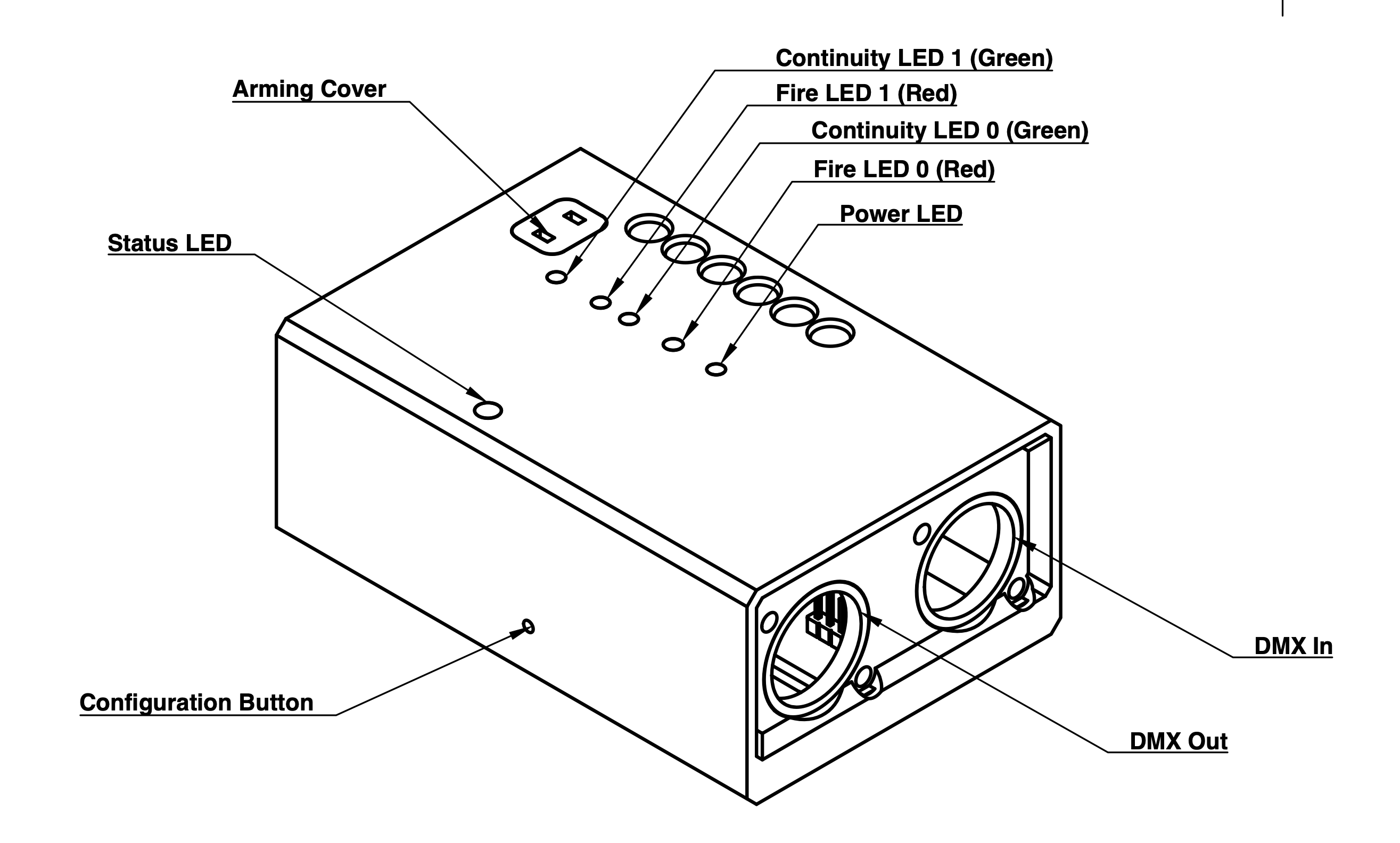
The Pico Pyro can be in one of three modes, these are indicated by the status LED.
By default the system enters active mode when turned on.
To enter setup mode the configuration button must be pressed while being turned on. Setup mode cannot be entered after booting.
If the system detects an invalid configuration during boot the system will enter failed mode. To resolved the system must be turned off and back on into setup mode.
| Channel | Description |
|---|---|
| 1 | Pyrotechnic Channel 0 Authorization |
| 2 | Pyrotechnic Channel 1 Authorization |
| 3 | Pyrotechnic Channel 0 Fire |
| 4 | Pyrotechnic Channel 1 Fire |
The DMX values to activate the different channels are specified in the configuration tool.
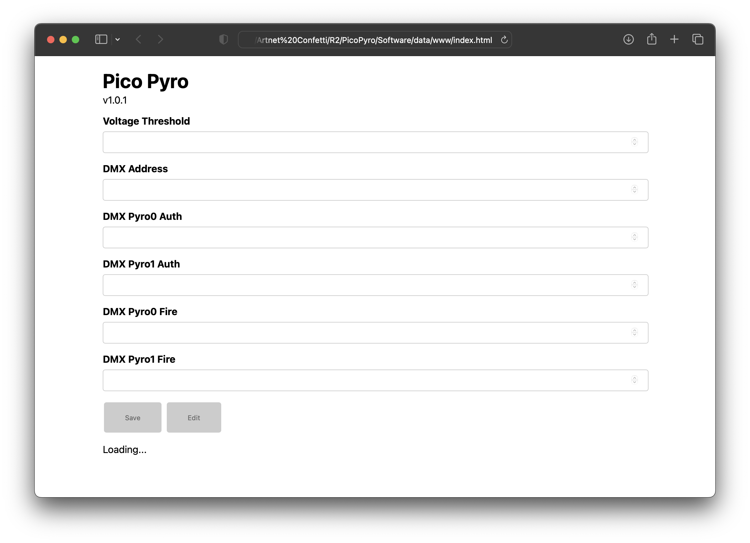
Once entering setup mode the system can be configured using the built-in website. This is accessed by connecting to the WiFi network that is broadcast and navigating to the IP address in the chosen browser.
SSID - PicoPyro
Password - itsathing
URL - http://10.66.0.1
The user should be presented with the following...
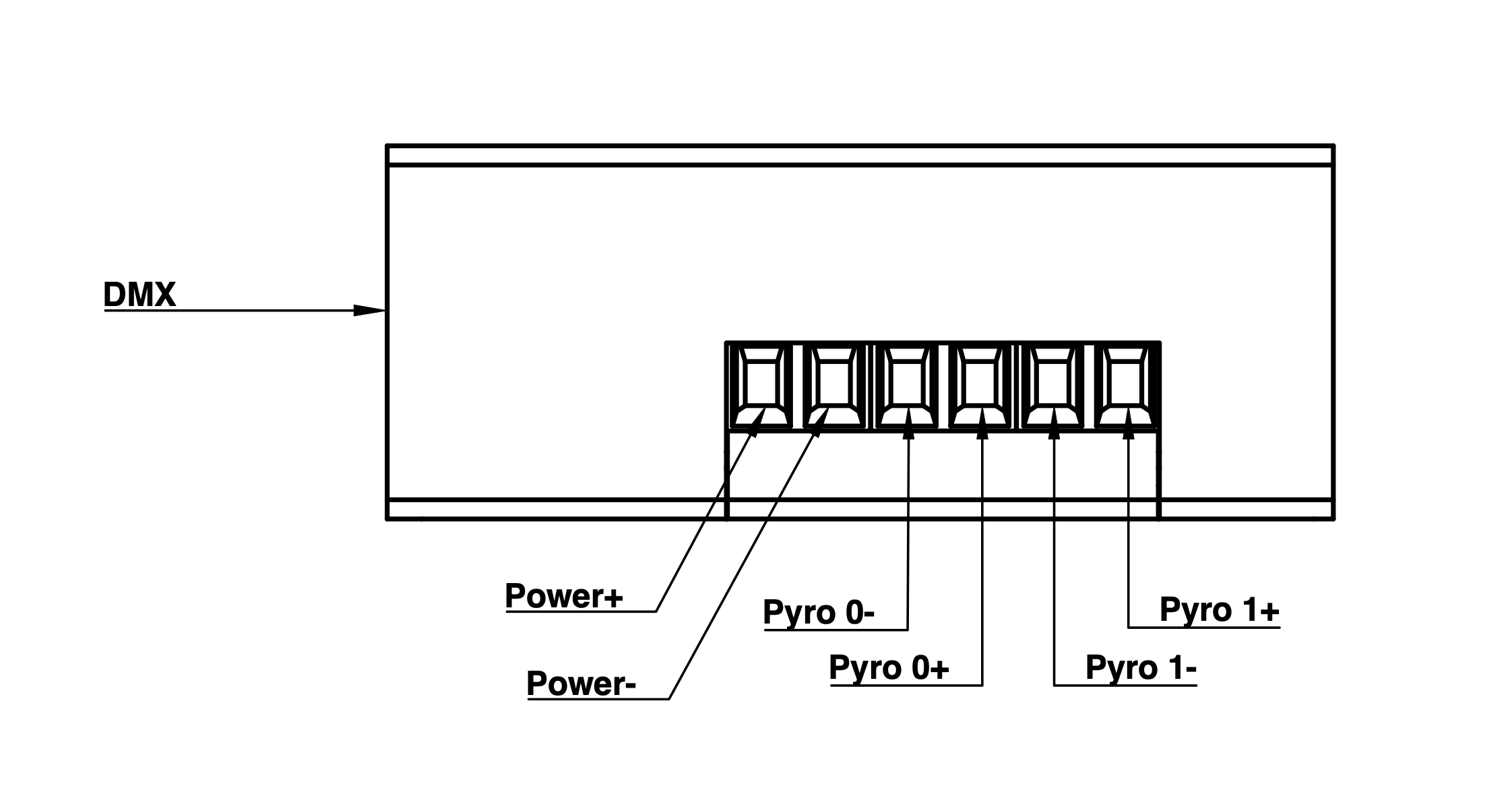
Ensure all connections are attached.
Arming cover can be removed for rehearsals to test the behaviour of the system without activating pyrotechnic channels.
When the arming cover is removed the channels are electrically disconnected and cannot fire. The continuity LEDs will temporarily stop working. Fire LEDs will work as expected but won't fire the pyrotechnic channels.
The recommended method of removing the arming cover is by placing a cable tie through the loop and pulling backwards.
Do not set the activation value to 255, this will increase the chance of accidental activation.
Instead use a selection of unique, different values.
The easiest way to integrate this system into lighting software is by patching 4 dimmer channels.
Voltage dividers are used for the continuity detection.
Low voltage dropout is in the voltage regulator.
We accept no responsibility for the consequences of activating a pyrotechnic.
| Qty | Value | Footprint | References |
|---|---|---|---|
| 5 | 10k | Resistor_SMD:R_0402_1005Metric | R201, R204, R211, R214, R701 |
| 5 | LED | LED_SMD:LED_0603_1608Metric | D201, D211, D401, D411, D601 |
| 4 | RPi_Hat:RPi_Hat_Mounting_Hole | , , , | |
| 4 | 500 | Resistor_SMD:R_0402_1005Metric | R202, R212, R401, R411 |
| 3 | 100n | Capacitor_SMD:C_0402_1005Metric | C101, C102, C301 |
| 3 | TB005-762-02BE | Custom:TB00576202BE | J201, J202, J501 |
| 2 | 0679H9100-05 | Custom:FUSC6125X279N | F201, F211 |
| 2 | 10u | Capacitor_SMD:C_0805_2012Metric_Pad1.18x1.45mm_HandSolder | C501, C502 |
| 2 | 150k | Resistor_SMD:R_0402_1005Metric | R203, R213 |
| 2 | 680 | Resistor_SMD:R_0402_1005Metric | R103, R104 |
| 2 | TPH9R506PL,LQ | Custom:TPCA8128L1Q | locked, locked |
| 1 | 120 | Resistor_SMD:R_0402_1005Metric | R102 |
| 1 | 1k | Resistor_SMD:R_0402_1005Metric | R601 |
| 1 | 2k | Resistor_SMD:R_0402_1005Metric | R101 |
| 1 | ADM2483xRW | Package_SO:SOIC-16W_7.5x10.3mm_P1.27mm | U101 |
| 1 | Conn_01x02 | Connector_PinHeader_2.54mm:PinHeader_1x02_P2.54mm_Vertical | J503 |
| 1 | Conn_01x02 | Connector_AMASS:AMASS_XT30U-F_1x02_P5.0mm_Vertical | J502 |
| 1 | Conn_01x03 | Connector_PinHeader_2.54mm:PinHeader_1x03_P2.54mm_Vertical | J103 |
| 1 | Conn_01x06 | Connector_PinSocket_2.54mm:PinSocket_1x06_P2.54mm_Vertical | J001 |
| 1 | DMP2120U-7 | Custom:SOT96P240X110-3N | locked |
| 1 | MEE1S0503SC | Converter_DCDC:Converter_DCDC_Murata_MEE1SxxxxSC_THT | PS101 |
| 1 | Pico | MCU_RaspberryPi_and_Boards:RPi_Pico_SMD_TH | U001 |
| 1 | TQL850CSV50 | Custom:SOIC127P600X170-9N | locked |
| 1 | TS11-674-43-BK-100-RA-D | Custom:TS1167443BK100RAD | locked |
| 1 | WS2812B | LED_SMD:LED_WS2812B_PLCC4_5.0x5.0mm_P3.2mm | D301 |
| 1 | XLR3 | Connector_Audio:Jack_XLR_Neutrik_NC3MAAH_Horizontal | J102 |
| 1 | XLR3 | Connector_Audio:Jack_XLR_Neutrik_NC3FAAH_Horizontal | J101 |
It measures 91 × 61 mm and has 2 copper layers, 1.6 mm thick.
50 parts, built around the TB005-762-02BE, 0679H9100-05, DMP2120U-7 and TQL850CSV50 RLG. The full list of its parts is on this page, with links to each part's symbol and footprint where PCBKit's library has them.
From the NathanRignall/PicoPyro repository on GitHub, at the commit this page was made from: the board is Hardware/PicoPyro.kicad_pcb and its schematic Hardware/PicoPyro.kicad_sch. PCBKit opens the board in the browser, with nothing to install.
Its repository states no licence, so its author keeps all rights: ask NathanRignall before reusing the design.

Krypthick/Prototype-Bras-Continuum
Ce repo contient les schemas, les cartes imprimées, les codes sources, etc du projet.

gobabygocarswithjoysticks/gbg-pcb
A PCB for controlling the motors in a go baby go car with joystick control

LucienMorey/parrot_imu
This design will host an IMU board for the Parody tripedal robotic platform. It will expose connect an IMU to the teensy 4.1 microcontroller with the ability to deliver this data over CAN bus and over an ethernet…


atom-dispencer/SolenoidEngine4
My 4th attempt (though the first public one) at building a 4-cylinder USB-powered solenoid engine desk ornament.

yukselturkomer/50w-buck-converter-stm32
Bu proje, STM32 mikrodenetleyici kullanılarak geliştirilmiş 50W kapasiteli bir Buck (Düşürücü) Konvertör sistemini ve bu sistemin kontrolünü sağlayan Nextion HMI (İnsan-Makine Arayüzü) tasarımını içermektedir.

fossasia/pslab-hardware
PSLab Hardware Design and Schematics https://pslab.io