2 layers165.1 × 100 mm

 nano13579/banana-split
hotswappable wireless split keyboard
Right split is an open-source printed circuit board by nano13579, from the nano13579/banana-split repository on GitHub, published under the GPL-3.0 licence. It is a 2-layer board of 193.8 × 100 mm with 74 parts on 64 nets, routed with 400 tracks and 75 vias.
Its parts include 36 diodes, 36 switches and 1 IC. It belongs with the keyboards and input boards and the nRF52 and nRF5x boards of this library.
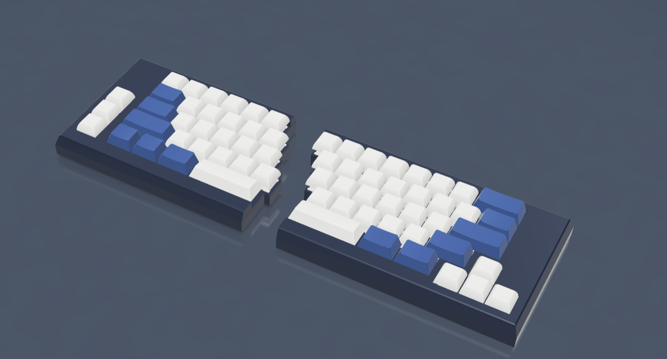
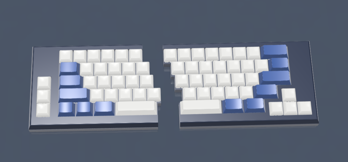
With a design similar to that of the UM-70, this split keeb is hotswappable, wireless, and ZMK supported. Both halves fit together like puzzle pieces and are powered by 3.7v rechargeable lithium ion batteries. The current case is made of a simple sandwich mount with openings for USB-C connection. I made this primarily because I wanted to make something unique and different from common split custom keyboard designs - I also learned a ton about matrixes and the functionality behind wireless split keebs in the process.
In the current design, there are no neopixels, rotary encoders, OLED screens, etc. because I was lazy but future iterations may include these features! There are also no current features for wrist support - so this might be added later as well. Stabiliziers aren't in the cad right now, but do fit into case & pcb.
Please note that a few footprints at the edge of the right hand keeb are upside down so that edge cut restrictions would not change dimensions. Therefore, all keycaps should be PBT OEM so as to not obstruct typing - although this is not shown in the design
| Qty | Value | Footprint | References |
|---|---|---|---|
| 36 | 1N4148 | Diode_THT:D_DO-35_SOD27_P7.62mm_Horizontal | D1, D2, D10, D11, D12, D13, D14, D15, D16, D17, D18, D19, D20, D21, D22, D23 +20 |
| 29 | SW_Push_45deg | kailhv4:MX-Hotswap-1U | SW1, SW2, SW10, SW11, SW12, SW13, SW14, SW15, SW17, SW18, SW19, SW20, SW21, SW22, SW24, SW25 +13 |
| 3 | SW_Push_45deg | kailhv4:MX-Hotswap-1.5U | SW16, SW32, SW33 |
| 1 | Battery_Cell | Connector_JST:JST_PH_S2B-PH-K_1x02_P2.00mm_Horizontal | BT1 |
| 1 | Nice_Nano_V2 | scotto:Nice_Nano_V2 | U1 |
| 1 | SW_Push_45deg | kailhv4:MX-Hotswap-3U | SW31 |
| 1 | SW_Push_45deg | kailhv4:MX-Hotswap-1.75U | SW29 |
| 1 | SW_Push_45deg | kailhv4:MX-Hotswap-2.25U | SW23 |
| 1 | SW_Push_45deg | kailhv4:MX-Hotswap-2U | SW8 |
It measures 193.8 × 100 mm and has 2 copper layers, 1.6 mm thick.
74 parts. The full list of its parts is on this page, with links to each part's symbol and footprint where PCBKit's library has them.
From the nano13579/banana-split repository on GitHub, at the commit this page was made from: the board is pcb/right_split/right_split.kicad_pcb and its schematic pcb/left_split/left_split.kicad_sch. PCBKit opens the board in the browser, with nothing to install.
Its repository publishes it under the GPL-3.0 licence: you may reuse it on that licence's terms (keep the author's notice, and for a copyleft licence share your changes alike).

hackclub/OnBoard
💡 Join 1,000 teenagers and make your first PCB with a $100 grant!

CRImier/MyKiCad
My KiCad boards. Can't be bothered uploading individually anymore, so here you go.

Teslafly/Dead-OpenBMS-dead
A scalable, open source battery management system

profdc9/RFBitBanger
A QRP digital transceiver created from readily available parts for off-the-grid maintenance


KaeptnBalu/Arduino_Spot_Welder_V3
This is the Kicad project for V3.1 The Arduino Board was not changed, only the Mosfet Board got a updgrade.


slu4coder/Minimal-UART-Computer-1-2
Legacy: Version 1 and 2 of my TTL-only CPU featuring UART I/O, an expansion port, 512KB SSD at up to 10MHz clock speed