2 layers152 × 88 mm
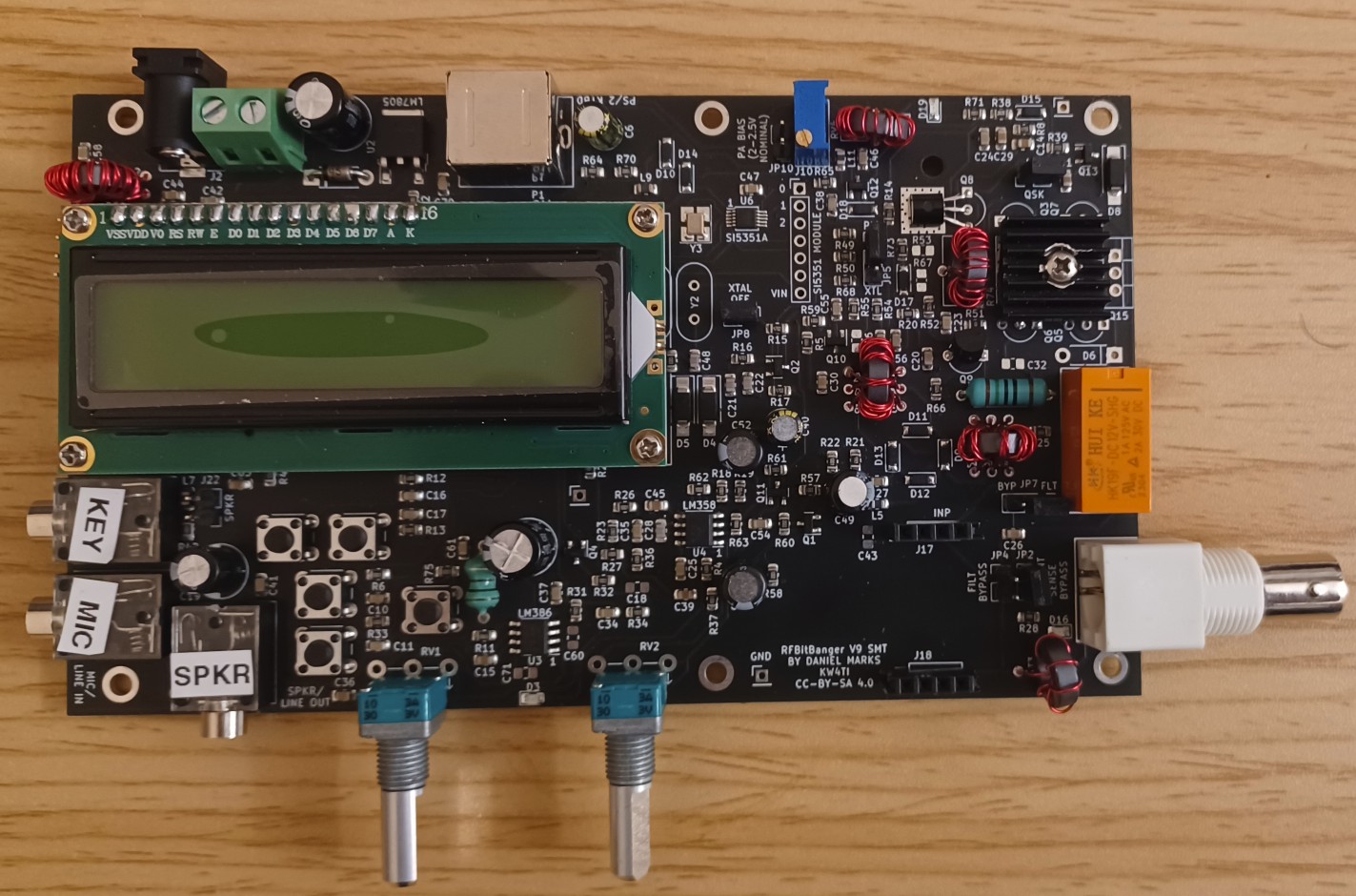
RFBitBangSMT
profdc9/RFBitBanger
A QRP digital transceiver created from readily available parts for off-the-grid maintenance
271 parts222

 profdc9/RFBitBanger222
A QRP digital transceiver created from readily available parts for off-the-grid maintenance
SerialResonantFilter is an open-source printed circuit board by profdc9, from the profdc9/RFBitBanger repository on GitHub. It is a 2-layer board of 72.4 × 72.4 mm with 74 parts on 77 nets, routed with 181 tracks and 15 vias.
Its parts include 58 capacitors, 8 connectors and 8 inductors.
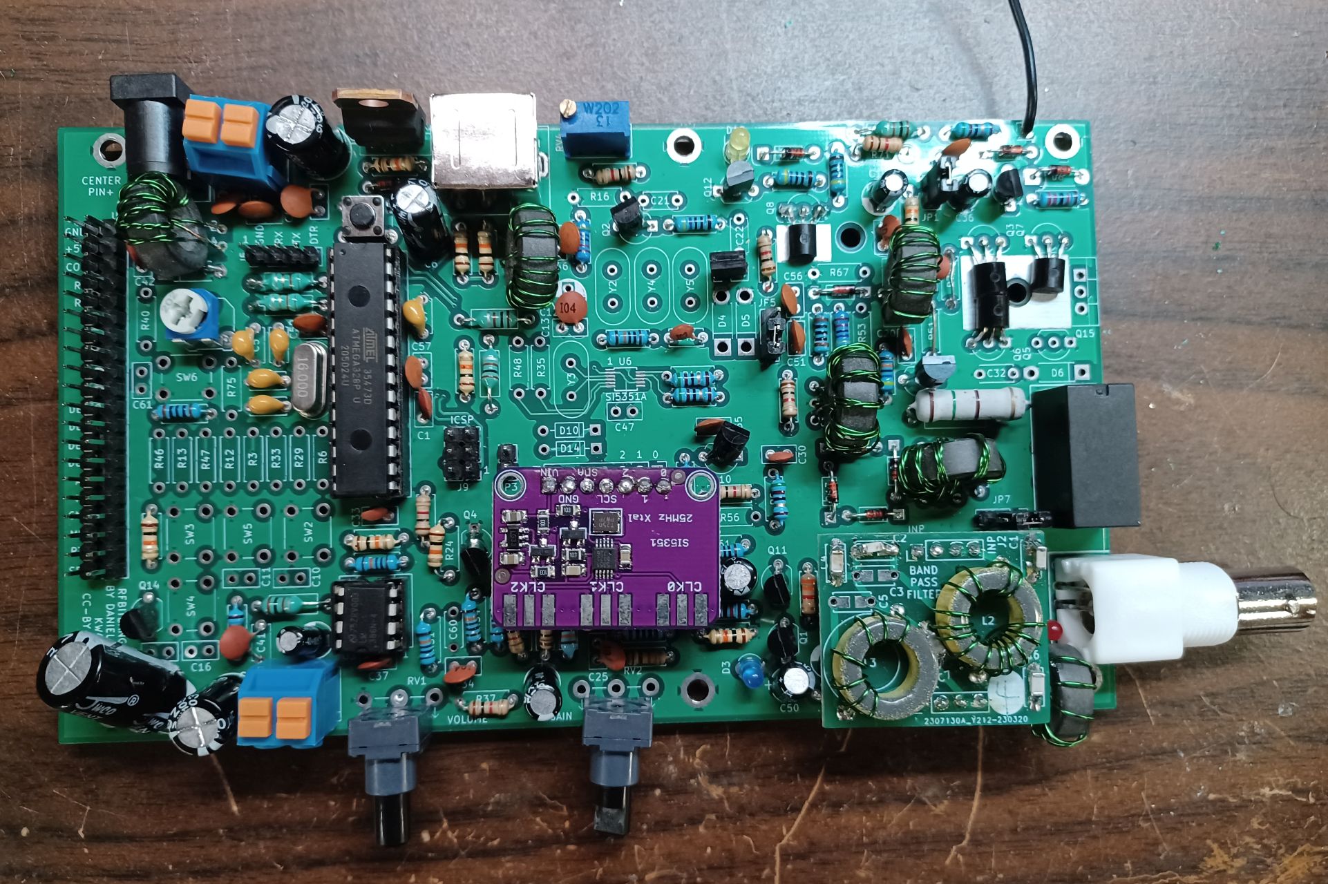
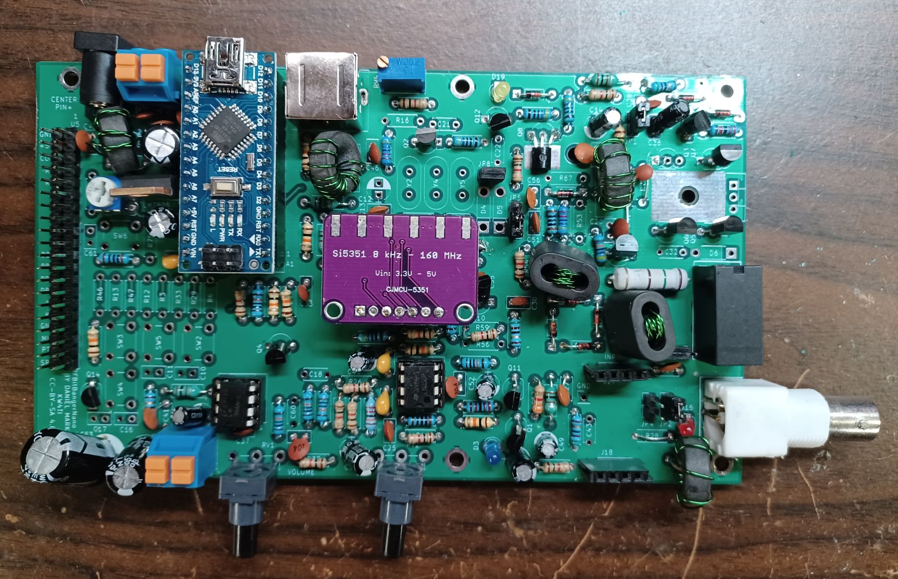
The RFBitBanger is an off-the-grid QRP radio. It is not just designed to be used off the grid, it is designed to be assembled and maintained off-the-grid. Most radios require specialized parts that would be difficult to obtain in an extreme parts shortage or in remote places. This radio is designed to be assembled and maintained using the most common jellybean components that might be in a hobbyist junkpile. It will mainly support low bandwidth/digital modes to make the most of limited power.
A presentation presented at the 2023 QSO Today conference on the RFBitBanger can be viewed on Youtube here.
Design goals:
The RFBitBanger folder is the schematic and PCB for the radio itself. The MatchTest is a PCB that has a directional coupler for measuring forward/reverse power as well as a reflection bridge to help match antenna impedance. The Code folder contains the current RFBitBanger code. The CAD directory contains FreeCAD parametric models and STL files. The Docs directory contains a guide to the transceiver and the details of the SCAMP digital mode implementation.
This design was started after a discuss on the Collapse OS mailing list about hardware is maintainable even without access to parts suppliers, for example Digikey/Mouser, etc. or even Amazon. Projects such as civboot seek to provide a means of resurrecting technology and infrastructure after a catastrophic event. This design is to provide a means of communication if other forms of communications become unavailable, especially in rural areas or urban environments with compromised infrastructure.
Any comments to profdc9 AT gmail.com.
| Qty | Value | Footprint | References |
|---|---|---|---|
| 7 | 1000 pF | Capacitor_SMD:C_1206_3216Metric_Pad1.33x1.80mm_HandSolder | C2, C4, C6, C37, C40, C57, C58 |
| 7 | 470 pF | Capacitor_SMD:C_1206_3216Metric_Pad1.33x1.80mm_HandSolder | C10, C11, C14, C31, C34, C51, C52 |
| 5 | 2200 pF | Capacitor_SMD:C_1206_3216Metric_Pad1.33x1.80mm_HandSolder | C17, C18, C21, C36, C39 |
| 4 | 100 pF | Capacitor_SMD:C_1206_3216Metric_Pad1.33x1.80mm_HandSolder | C41, C44, C46, C47 |
| 4 | 150 pF | Capacitor_SMD:C_1206_3216Metric_Pad1.33x1.80mm_HandSolder | C8, C13, C30, C33 |
| 4 | 330 pF | Capacitor_SMD:C_1206_3216Metric_Pad1.33x1.80mm_HandSolder | C1, C5, C29, C32 |
| 4 | 680 pF | Capacitor_SMD:C_1206_3216Metric_Pad1.33x1.80mm_HandSolder | C15, C20, C35, C38 |
| 3 | C3 | Capacitor_SMD:C_1206_3216Metric_Pad1.33x1.80mm_HandSolder | C3, C9, C16 |
| 3 | C7 | Capacitor_SMD:C_1206_3216Metric_Pad1.33x1.80mm_HandSolder | C7, C12, C19 |
| 3 | INP | Connector_PinSocket_2.54mm:PinSocket_1x04_P2.54mm_Vertical | J3, J5, J7 |
| 3 | OUT | Connector_PinSocket_2.54mm:PinSocket_1x04_P2.54mm_Vertical | J4, J6, J8 |
| 2 | 1500 pF | Capacitor_SMD:C_1206_3216Metric_Pad1.33x1.80mm_HandSolder | C55, C56 |
| 2 | 220 pF | Capacitor_SMD:C_1206_3216Metric_Pad1.33x1.80mm_HandSolder | C43, C48 |
| 2 | 33 pF | Capacitor_SMD:C_1206_3216Metric_Pad1.33x1.80mm_HandSolder | C49, C50 |
| 2 | 47 pF | Capacitor_SMD:C_1206_3216Metric_Pad1.33x1.80mm_HandSolder | C42, C45 |
| 2 | 68 pF | Capacitor_SMD:C_1206_3216Metric_Pad1.33x1.80mm_HandSolder | C53, C54 |
| 1 | 0.18 uH | SerialResonantFilter:L_Toroid_Horizontal_D12.7mm_Compact | L4 |
| 1 | 0.36 uH | SerialResonantFilter:L_Toroid_Horizontal_D12.7mm_Compact | L3 |
| 1 | 0.39 uH | SerialResonantFilter:L_Toroid_Horizontal_D12.7mm_Compact | L1 |
| 1 | 0.68 uH | SerialResonantFilter:L_Toroid_Horizontal_D12.7mm_Compact | L6 |
| 1 | 0.77 uH | SerialResonantFilter:L_Toroid_Horizontal_D12.7mm_Compact | L2 |
| 1 | 1.45 uH | SerialResonantFilter:L_Toroid_Horizontal_D12.7mm_Compact | L5 |
| 1 | C1 | SerialResonantFilter:C_Disc_D5.0mm_W2.5mm_P5.00mm_Dual | C22 |
| 1 | C2 | SerialResonantFilter:C_Disc_D5.0mm_W2.5mm_P5.00mm_Dual | C24 |
| 1 | C3 | SerialResonantFilter:C_Disc_D5.0mm_W2.5mm_P5.00mm_Dual | C23 |
| 1 | C4 | SerialResonantFilter:C_Disc_D5.0mm_W2.5mm_P5.00mm_Dual | C25 |
| 1 | C5 | SerialResonantFilter:C_Disc_D5.0mm_W2.5mm_P5.00mm_Dual | C27 |
| 1 | C6 | SerialResonantFilter:C_Disc_D5.0mm_W2.5mm_P5.00mm_Dual | C28 |
| 1 | C7 | SerialResonantFilter:C_Disc_D5.0mm_W2.5mm_P5.00mm_Dual | C26 |
| 1 | INP | Pin_Headers:Pin_Header_Straight_1x04_Pitch2.54mm | J2 |
| 1 | L2 | SerialResonantFilter:L_Toroid_Horizontal_D12.7mm_Compact | L7 |
| 1 | L3 | SerialResonantFilter:L_Toroid_Horizontal_D12.7mm_Compact | L8 |
| 1 | OUT | Pin_Headers:Pin_Header_Straight_1x04_Pitch2.54mm | J1 |
It measures 72.4 × 72.4 mm and has 2 copper layers, 1.6 mm thick.
74 parts. The full list of its parts is on this page, with links to each part's symbol and footprint where PCBKit's library has them.
From the profdc9/RFBitBanger repository on GitHub, at the commit this page was made from: the board is SerialResonantFilterSMT/SerialResonantFilter.kicad_pcb. PCBKit opens the board in the browser, with nothing to install.
Its repository states no licence, so its author keeps all rights: ask profdc9 before reusing the design.
profdc9/RFBitBanger
A QRP digital transceiver created from readily available parts for off-the-grid maintenance

profdc9/RFBitBanger
A QRP digital transceiver created from readily available parts for off-the-grid maintenance

profdc9/RFBitBanger
A QRP digital transceiver created from readily available parts for off-the-grid maintenance

profdc9/RFBitBanger
A QRP digital transceiver created from readily available parts for off-the-grid maintenance

profdc9/RFBitBanger
A QRP digital transceiver created from readily available parts for off-the-grid maintenance

profdc9/RFBitBanger
A QRP digital transceiver created from readily available parts for off-the-grid maintenance

profdc9/RFBitBanger
A QRP digital transceiver created from readily available parts for off-the-grid maintenance

profdc9/RFBitBanger
A QRP digital transceiver created from readily available parts for off-the-grid maintenance

profdc9/RFBitBanger
A QRP digital transceiver created from readily available parts for off-the-grid maintenance

hackclub/OnBoard
💡 Join 1,000 teenagers and make your first PCB with a $100 grant!

CRImier/MyKiCad
My KiCad boards. Can't be bothered uploading individually anymore, so here you go.

Teslafly/Dead-OpenBMS-dead
A scalable, open source battery management system


KaeptnBalu/Arduino_Spot_Welder_V3
This is the Kicad project for V3.1 The Arduino Board was not changed, only the Mosfet Board got a updgrade.


slu4coder/Minimal-UART-Computer-1-2
Legacy: Version 1 and 2 of my TTL-only CPU featuring UART I/O, an expansion port, 512KB SSD at up to 10MHz clock speed

friction07/corne-xiao
This is a modified version of the corne keyboard by foostan. It is wireless and uses zmk firmware. - uses Seeed Studio XIAO nRF52840 - supports rotary encoder on each half - supports nice!view - has a power button and…