2 layers308.8 × 130.3 mm
CyberKeeb2040
zli117/CyberKeeb2040
Hardware design for a mechanical keyboard based on RP2040 that also has a Pi Zero onboard.
182 parts98CC-BY-SA-4.0

 Nadoooor/Eruca-Sync
i want to build a smart greenhouse agriculture system with actuators to maintain temperature, soil moisture, and light intensity for plant growth. why? i want to make a smart greenhouse that can make a suitable environment for the plant to grow, so I can plant new plants in my region and try them.
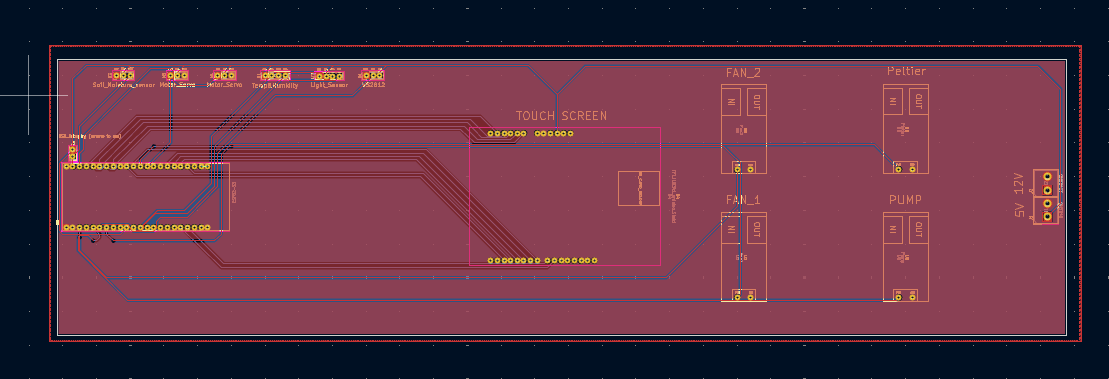
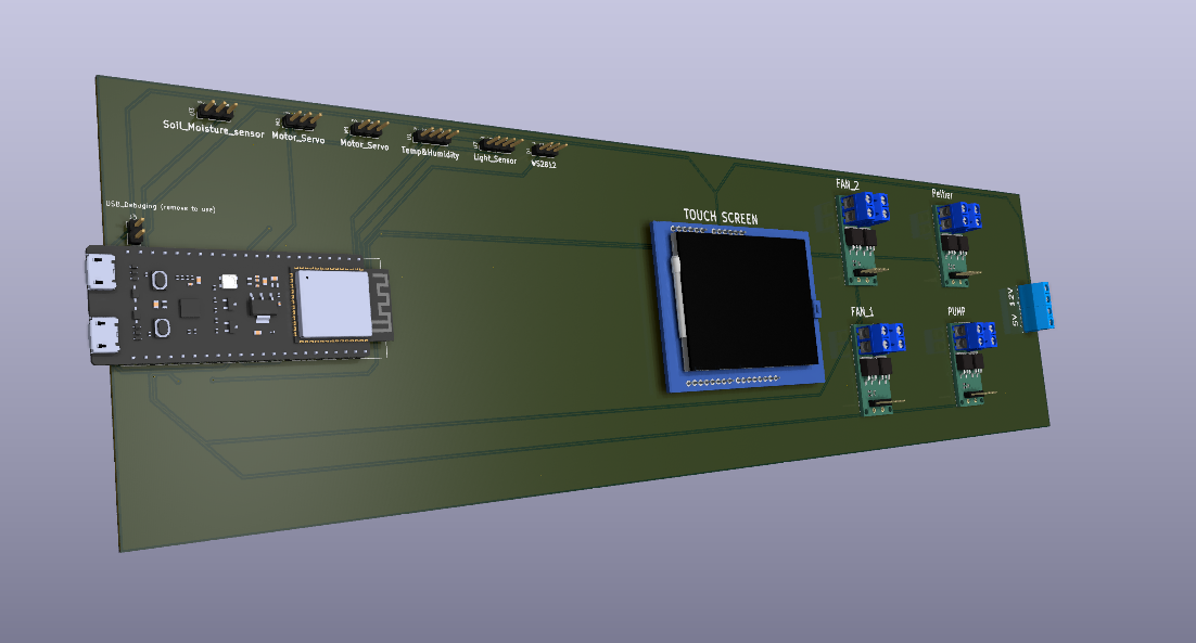
Cap S2 is an open-source printed circuit board by Nadoooor, from the Nadoooor/Eruca-Sync repository on GitHub, published under the MIT licence. It is a 2-layer board of 380.3 × 103.7 mm with 15 parts on 55 nets, routed with 186 tracks and 13 vias.
It is built around the ESP32-S3 and WS2812. Its parts include 9 ICs, 3 connectors and 1 diode. It belongs with the robots and motor control boards and the ESP32 boards of this library.


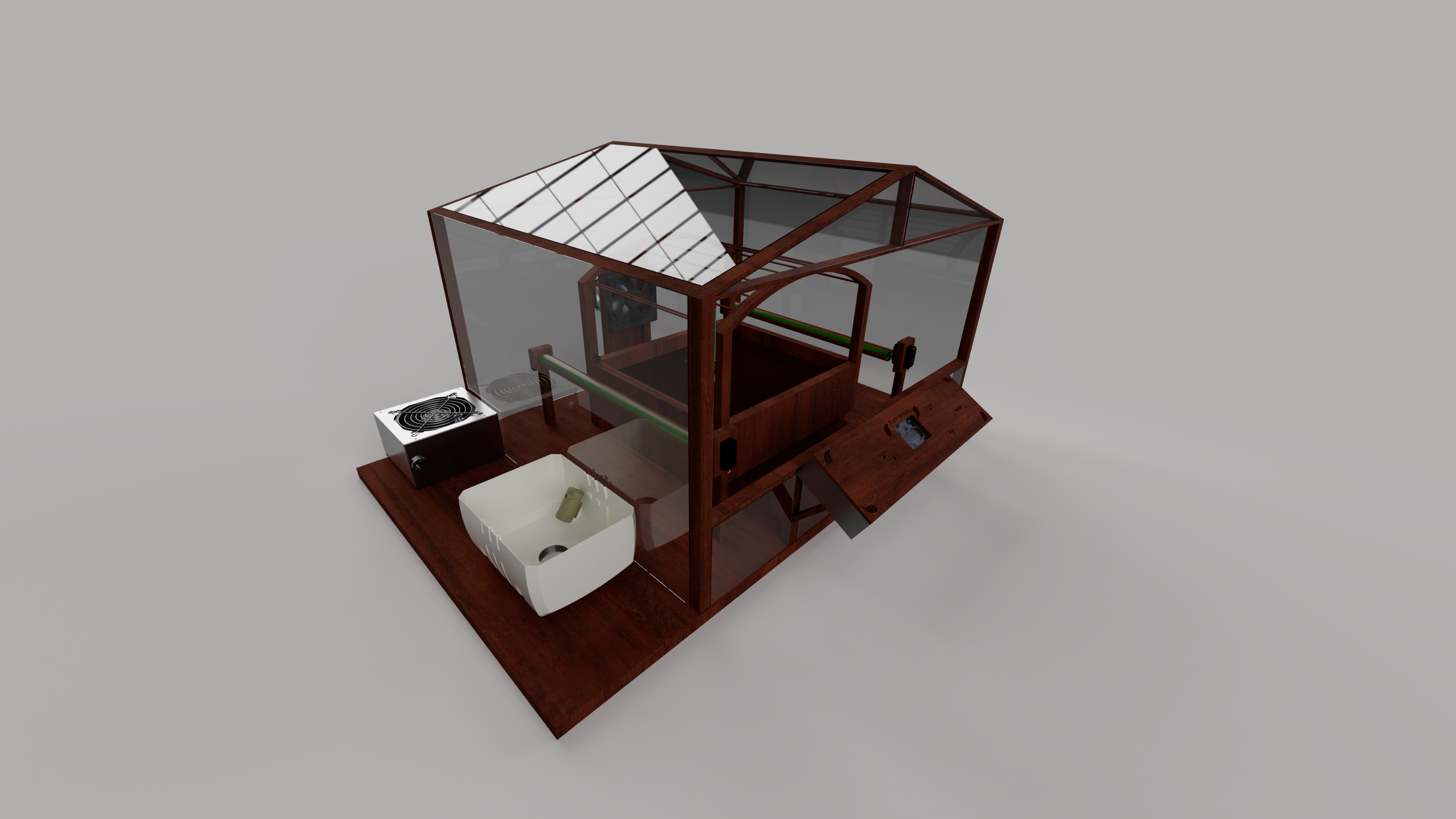
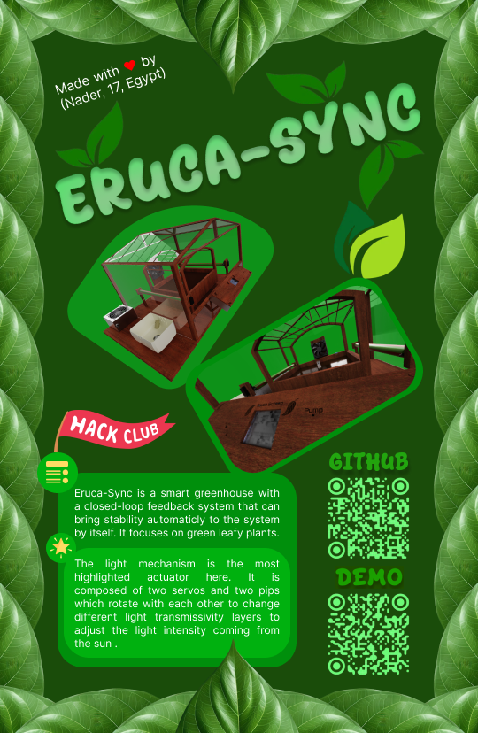
A smart greenhouse with a closed-loop feedback system that can bring stability automatically to the system by itself. It focuses on green leafy plants and on three parameters.
It has actuators that are responible of making the anti-changes that reverse any changes that occur in the environment, like temperature rise, soil drought, and over-light on the green leafy plants.
I made this because there are plants that I really want to try, but I can't plant them in my home because there is no suitable environment for them. So, the project will provide these plants with their suitable environment. For Example, around my home, I can't plant Eruca (Arugula) because of the direct sunlight and the high temperature. I really want to try planting Arugula, so I thought about how to plant it around my home, but with minimal effort. So, I got this idea to make a self-balancing environment for the Arugula or any plant species.
The light mechanism is the most highlighted actuator here. It is composed of two servos and two pips, which rotate with each other to change different light transmissivity layers to increase the light intensity coming from the sun or decrease it.
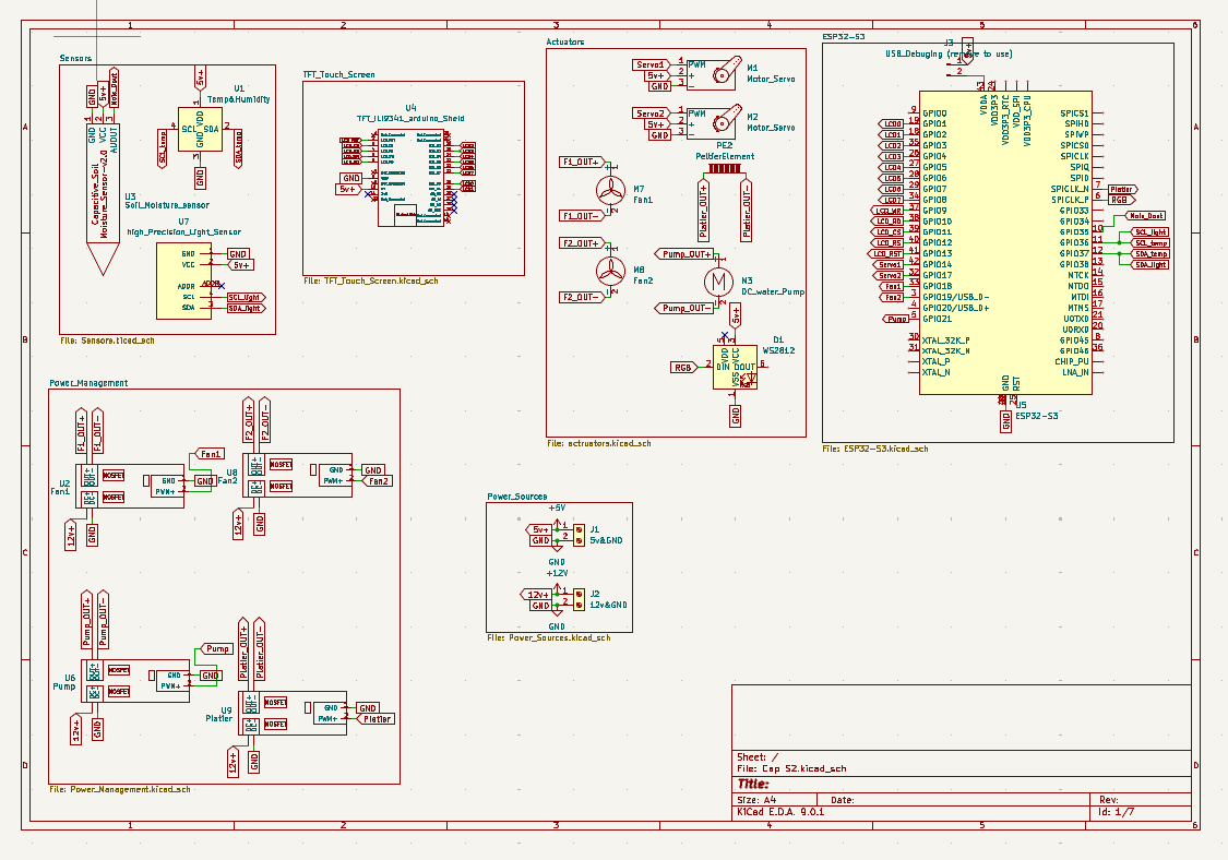
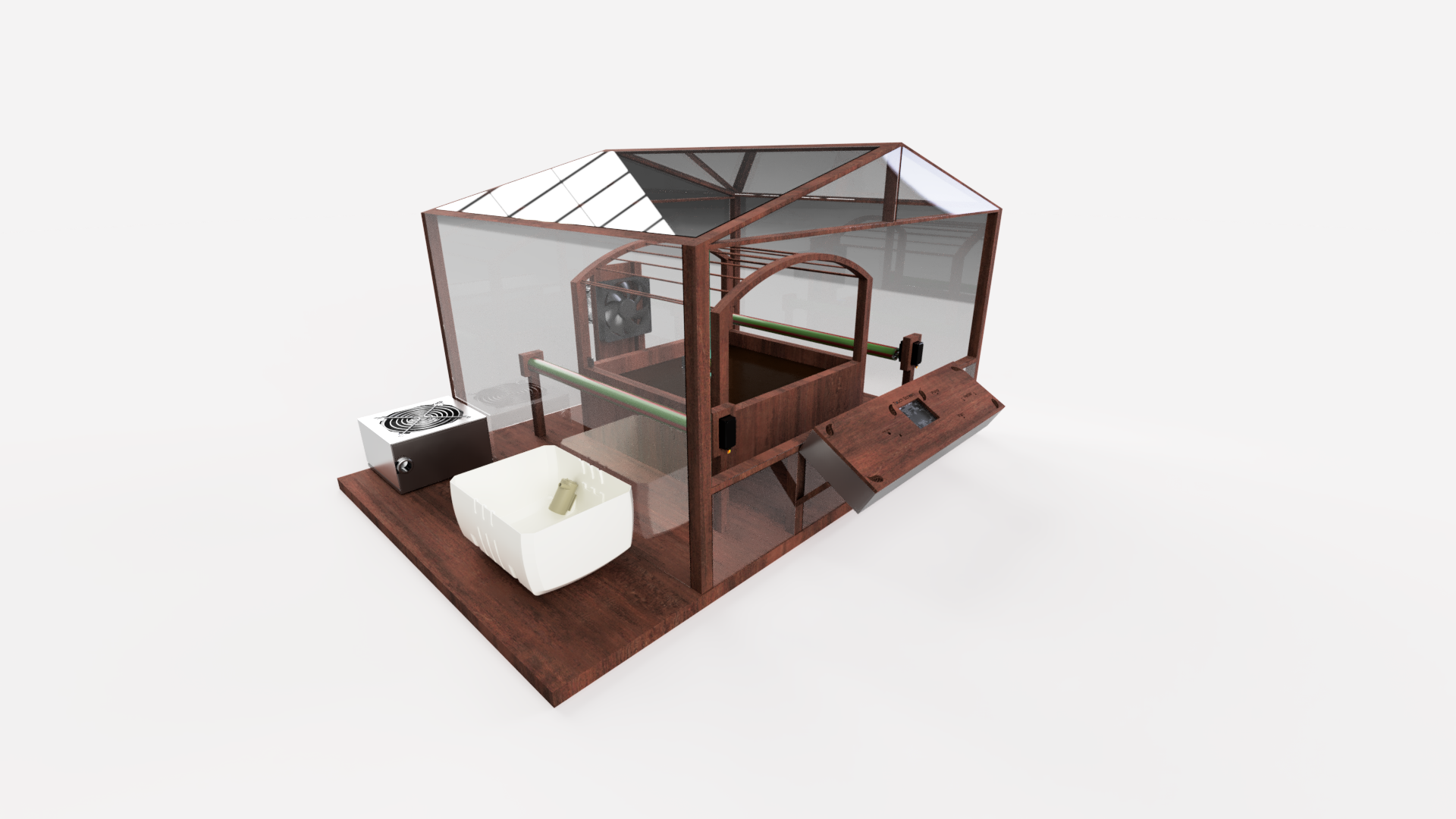
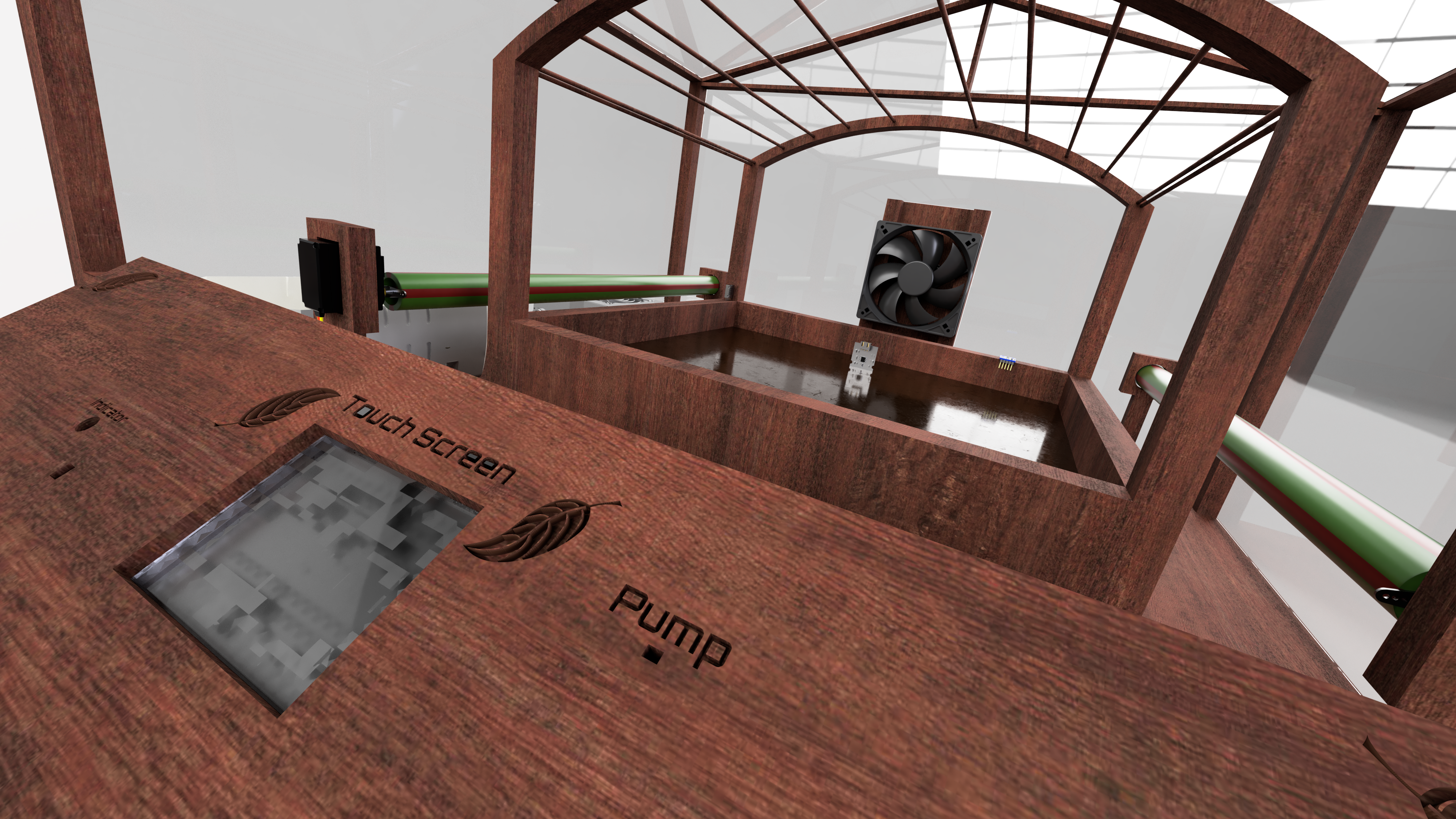
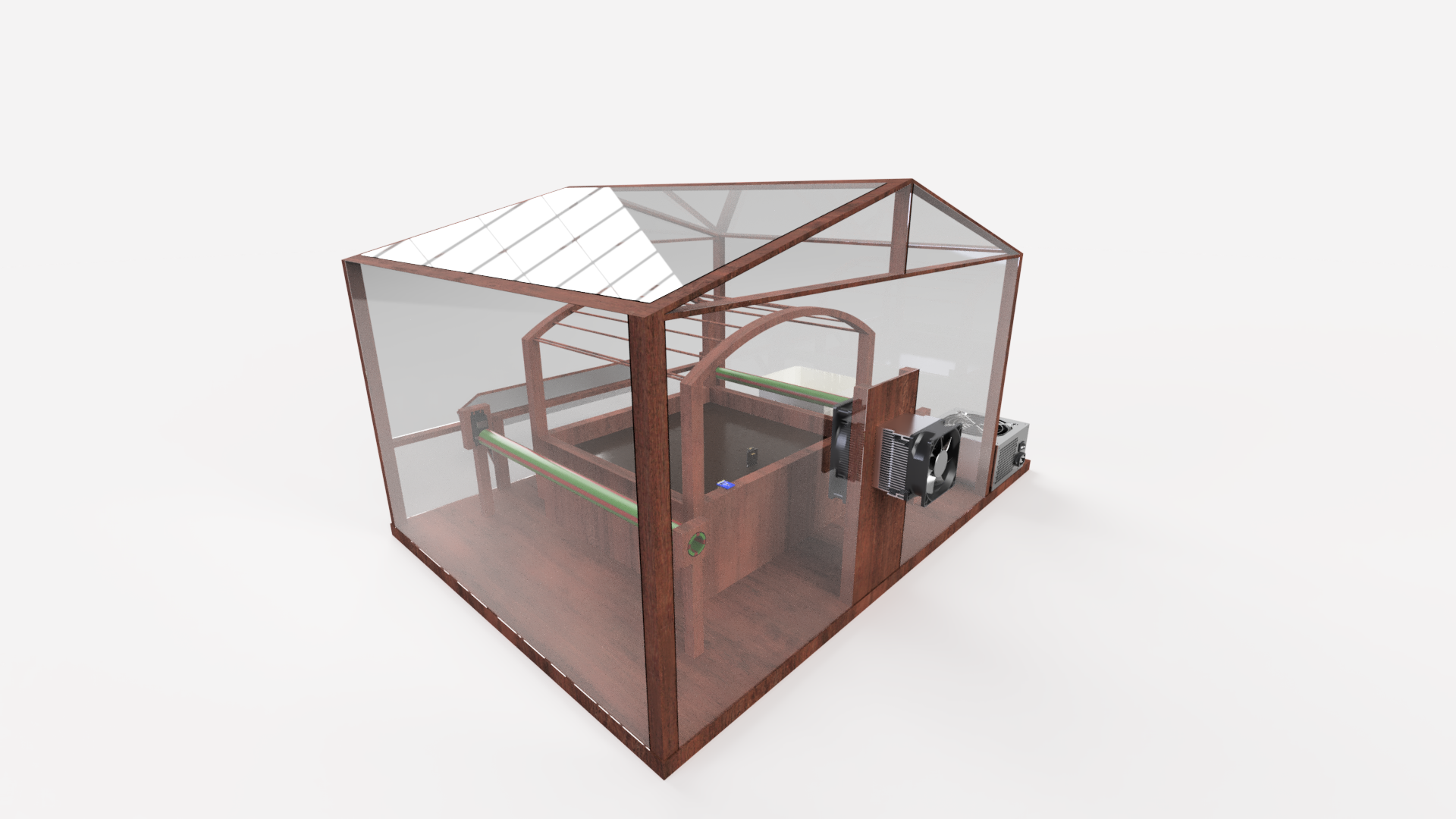
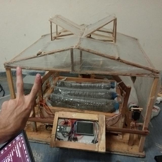
[!NOTE] Here you are the Onshape Docs. Also the build journal here
| Item Name | purchase links | Quantity | Price Per Unit | Total |
|---|---|---|---|---|
| FS5106R Servo Motor 360° Continuous 6 kg.cm Plastic Gears | Link | 2 | $7.4 | $14.8 |
| AM-2320 Temperature & Humidity Calibrated Sensor | Link | 1 | $3.28 | $3.28 |
| NeoPixel Stick 8-bit WS2812 5050 RGB LED | Link | 6 | $0.84 | $5.04 |
| Capacitive Analog Soil Moisture Sensor V2.0 | Link | 1 | $1.87 | $1.87 |
| BH1750 Light Calibrated Sensor | Link | 5 | $1.31 | $6.55 |
| Water Pump 3-6Vdc Mini 120L/H | Link | 1 | $0.84 | $0.84 |
| Thermoelectric Cooler 40x40mm - Peltier | Link | 1 | $2.81 | $2.81 |
| Aluminum Heatsink HS.13 Size 40x40x11 mm | Link | 1 | $0.52 | $0.52 |
| Kit MOSFET 15A 400W - Trigger Switch Drive Module | Link | 5 | $0.84 | $4.22 |
| PC Old Power Supply - 200W | Link | 1 | $2 | $2 |
| Old PC CPU Cooler with its Fan | Link | 1 | $5.62 | $5.62 |
| Old PC Fan 12cm | Link | 1 | $1.56 | $1.56 |
| Water Container (Any bottle or box) | Link | 1 | $1.3 | $1.3 |
| Wood with the dimensions (all the dimensions are in the onshape) | Bro any Cabinetmaker you don't need a link for that but At least this will help (For me i used recycled wood from my school) | ~~~ | Vary | Vary |
| LCD TFT 2.8 inch Touch Display with ILI9341 Driver 8bit Parallel | Link | 1 | $12.18 | $12.18 |
| ESP32-S3-N16R8 Development Board WIFI and Bluetooth | Link | 1 | $14.06 | $14.06 |
| PVC pipes as the rotation axies | As well as the wood (plz don't buy it online it is so cheap out there) | 2 x 0.5 meter | $3 | $6 |
| Plastic baggs or plastic sheets | Recycled as well | ~~~ | ~~~ | ~~~ |
| Jumper Wires | Link | 60 | $0.019 | $1.14 |
| Some Nails | The same place as the pipes | 30 | $0.027 | $0.8 |
| MDF Fast Adhesive Glue | Link | 2 | $3.18 | $6.36 |
| PCB | Link | 1 | $20 | $20 |
| Shipping | ~~~~~~~~~~ | ~~~ | ~~~ | $6.74 |
| Total | ~~~~~~~~~~ | ~~~ | ~~~ | $117.69 |
| Qty | Value | Footprint | References |
|---|---|---|---|
| 2 | Motor_Servo | Connector_PinHeader_2.54mm:PinHeader_1x03_P2.54mm_Vertical | M1, M2 |
| 1 | 12v&GND | TerminalBlock_Altech:Altech_AK100_1x02_P5.00mm | J2 |
| 1 | 5v&GND | TerminalBlock_Altech:Altech_AK100_1x02_P5.00mm | J1 |
| 1 | ESP32-S3 | MCUs:ESP32-S3-DEVKITC-1 | U5 |
| 1 | Fan1 | MCUs:MOSFET_KIT | U2 |
| 1 | Fan2 | MCUs:MOSFET_KIT | U8 |
| 1 | Light_Sensor | Connector_PinHeader_2.54mm:PinHeader_1x04_P2.54mm_Vertical | U7 |
| 1 | Platier | MCUs:MOSFET_KIT | U9 |
| 1 | Pump | MCUs:MOSFET_KIT | U6 |
| 1 | Soil_Moisture_sensor | Connector_PinHeader_2.54mm:PinHeader_1x03_P2.54mm_Vertical | U3 |
| 1 | TFT_ILI9341_arduino_Sheid | RAM:TFT_SCREEN | U4 |
| 1 | Temp&Humidity | Connector_PinHeader_2.54mm:PinHeader_1x04_P2.54mm_Vertical | U1 |
| 1 | USB_Debuging (remove to use) | Connector_PinHeader_2.54mm:PinHeader_1x02_P2.54mm_Vertical | J3 |
| 1 | WS2812 | Connector_PinHeader_2.54mm:PinHeader_1x03_P2.54mm_Vertical | D1 |
It measures 380.3 × 103.7 mm and has 2 copper layers, 1.6 mm thick.
15 parts, built around the ESP32-S3 and WS2812. The full list of its parts is on this page, with links to each part's symbol and footprint where PCBKit's library has them.
From the Nadoooor/Eruca-Sync repository on GitHub, at the commit this page was made from: the board is PCB/Cap S2.kicad_pcb and its schematic PCB/Cap S2.kicad_sch. PCBKit opens the board in the browser, with nothing to install.
Its repository publishes it under the MIT licence: you may reuse it on that licence's terms (keep the author's notice, and for a copyleft licence share your changes alike).
zli117/CyberKeeb2040
Hardware design for a mechanical keyboard based on RP2040 that also has a Pi Zero onboard.

ryomuk/TangNanoDCJ11MEM
Memory system and UART implemented on Tang Nano 20K for DEC DCJ11 PDP-11 Processor


cherry-embedded/HSCanT-hardware
HSCanT is a USB to 4-channel CAN FD tool designed based on the HPM5321 chip.

Duckle29/Vitamins-included
This repo holds a variation of the lets split. This board requires no soldering


