
2 layers308.8 × 130.3 mm
CyberKeeb2040
zli117/CyberKeeb2040
Hardware design for a mechanical keyboard based on RP2040 that also has a Pi Zero onboard.
182 parts98CC-BY-SA-4.0

 Nadoooor/BoxPad
A macropad in a cheese box, I'm just DIYing without printing anything.
BoxPad PCB is an open-source printed circuit board by Nadoooor, from the Nadoooor/BoxPad repository on GitHub, published under the MIT licence. It is a 2-layer board of 81 × 72.5 mm with 20 parts on 25 nets, routed with 84 tracks and 0 vias.
It is built around the WS2812. Its parts include 9 diodes, 9 switches and 2 ICs. It belongs with the keyboards and input boards and the RP2040 boards of this library.
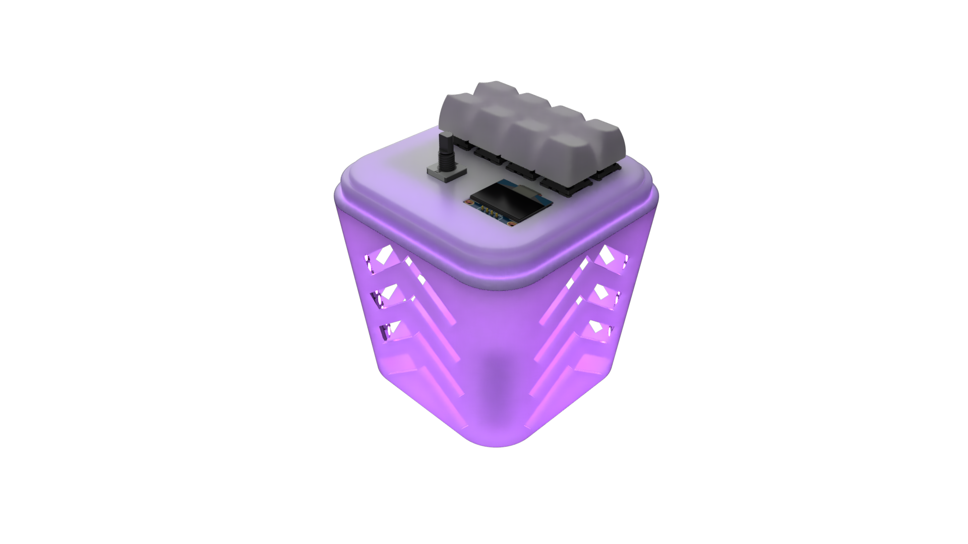
A macropad in a cheese box. This is a macropad made from scratch with MX switches, and it can be totaly made by DIYing (Recycling, and handwiring), or by just printing the case and the PCB.
Well, I have many hardware components and I want to make something with them, but 3D printing and PCB printing in Egypt costs so much, so gonna DIY it from scratch.
[!NOTE] AI helped a lil with the firmware DOCS because KMK & QMK are kinda outdated
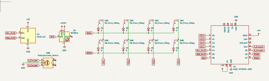
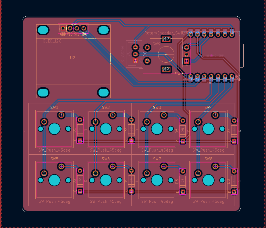
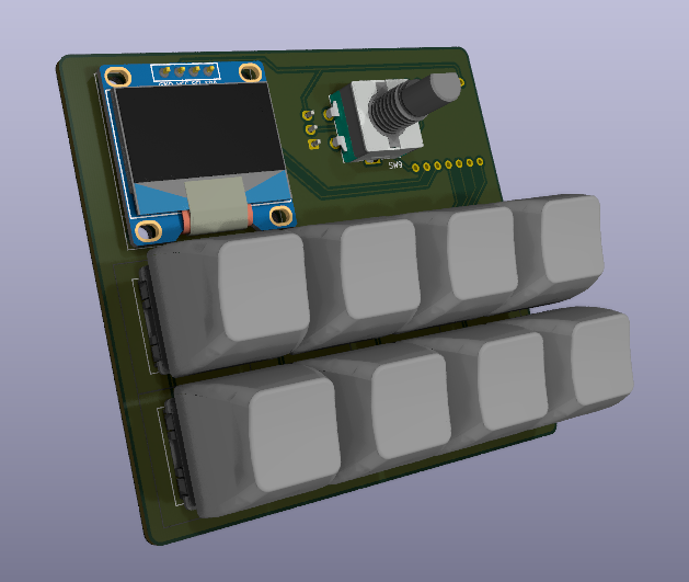
[!NOTE] Here you are the Fusion Assembly
You will find this video Here
| Qty | Value | Footprint | References |
|---|---|---|---|
| 8 | D | Diode_THT:D_DO-35_SOD27_P7.62mm_Horizontal | D1, D2, D3, D4, D5, D6, D7, D8 |
| 8 | SW_Push_45deg | My_Footprint:SW_Cherry_MX_1.00u_PCB_Wtih_3D | SW1, SW2, SW3, SW4, SW5, SW6, SW7, SW8 |
| 1 | OLED_I2C | Display-extra:Display_128x64_096_I2C | U2 |
| 1 | RotaryEncoder_Switch | Rotary_Encoder:RotaryEncoder_Alps_EC11E-Switch_Vertical_H20mm | SW9 |
| 1 | WS2812 | Connector_JST:JST_XH_B3B-XH-A_1x03_P2.50mm_Vertical | D9 |
| 1 | XIAO-RP2040-SMD | Seeed Studio XIAO Series Library:XIAO-RP2040-DIP | U1 |
zli117/CyberKeeb2040
Hardware design for a mechanical keyboard based on RP2040 that also has a Pi Zero onboard.

ryomuk/TangNanoDCJ11MEM
Memory system and UART implemented on Tang Nano 20K for DEC DCJ11 PDP-11 Processor


cherry-embedded/HSCanT-hardware
HSCanT is a USB to 4-channel CAN FD tool designed based on the HPM5321 chip.

Duckle29/Vitamins-included
This repo holds a variation of the lets split. This board requires no soldering


It measures 81 × 72.5 mm and has 2 copper layers, 1.6 mm thick.
20 parts, built around the WS2812. The full list of its parts is on this page, with links to each part's symbol and footprint where PCBKit's library has them.
From the Nadoooor/BoxPad repository on GitHub, at the commit this page was made from: the board is BoxPad_PCB/BoxPad_PCB.kicad_pcb and its schematic BoxPad_PCB/BoxPad_PCB.kicad_sch. PCBKit opens the board in the browser, with nothing to install.
Its repository publishes it under the MIT licence: you may reuse it on that licence's terms (keep the author's notice, and for a copyleft licence share your changes alike).