
2 layers99.1 × 99.1 mm
TangNanoDCJ11MEM
ryomuk/TangNanoDCJ11MEM
Memory system and UART implemented on Tang Nano 20K for DEC DCJ11 PDP-11 Processor
45 parts86MIT

 zli117/CyberKeeb204098
Hardware design for a mechanical keyboard based on RP2040 that also has a Pi Zero onboard.
CyberKeeb2040 is an open-source printed circuit board by zli117, from the zli117/CyberKeeb2040 repository on GitHub, published under the CC-BY-SA-4.0 licence. It is a 2-layer board of 308.8 × 130.3 mm with 182 parts on 155 nets, routed with 2,145 tracks and 709 vias.
It is built around the WS2812. Its parts include 84 diodes, 69 switches, 5 resistors, 5 connectors and 2 capacitors. It belongs with the keyboards and input boards and the RP2040 and Raspberry Pi (Linux) boards of this library.
A mechnical keyboard and a cyberdeck. Powered by PicoMK for communication between RP2040 and Pi Zero. Watch the demo on YouTube 👇.
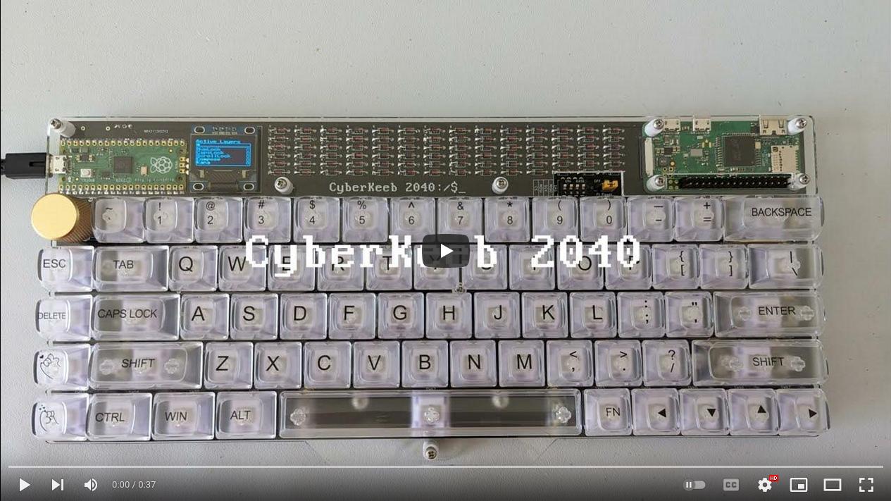
V2 parts list and build instructions
V1 parts list and build instructions
Everything is in PCB/MainBoard dir. Designed with Kicad 7.0. Make sure Perfect DOS VGA 437 Font is intalled on Windows, or if you use Arch, install the ttf-perfectdos package. PCB/MainBoard/Gerber dir contains the Gerber files for three fab houses: JLCPCB, PCBWay, and OSHPark. For JLCPCB and PCBWay, make sure to select the Castellated Holes option (this will increase the price, but I found it necessary for good castellated holes).
The frame has three acrylic plates and is held together with screws and standoffs.
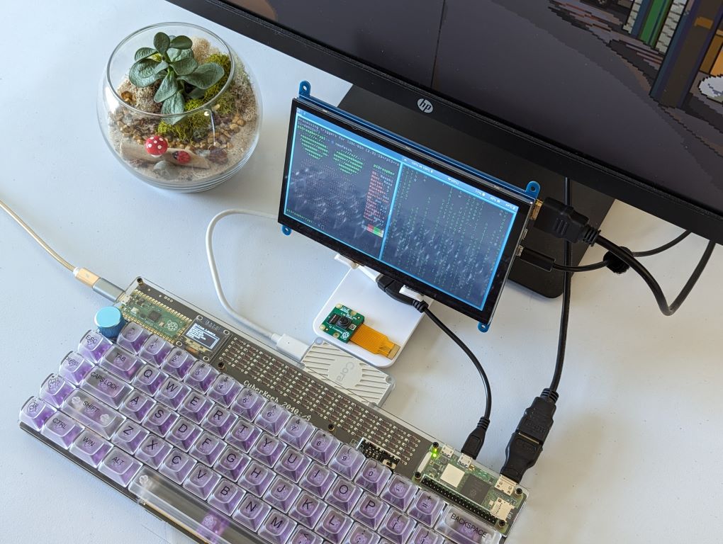
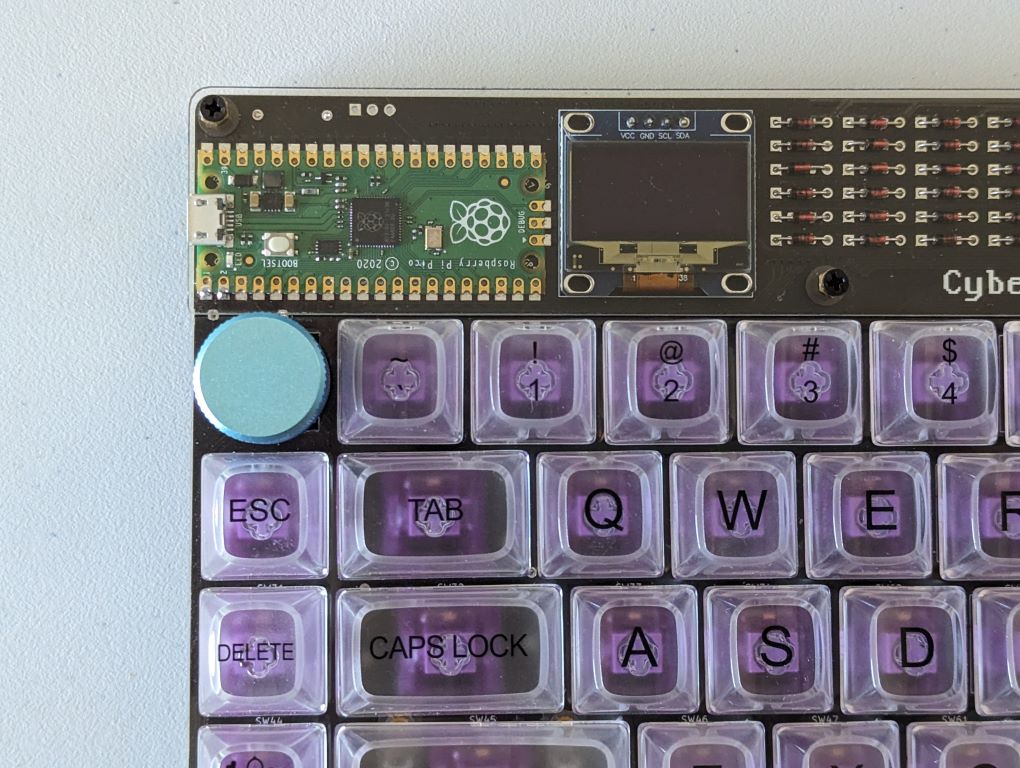
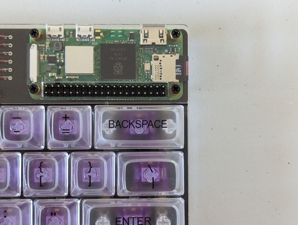
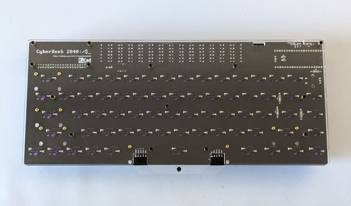
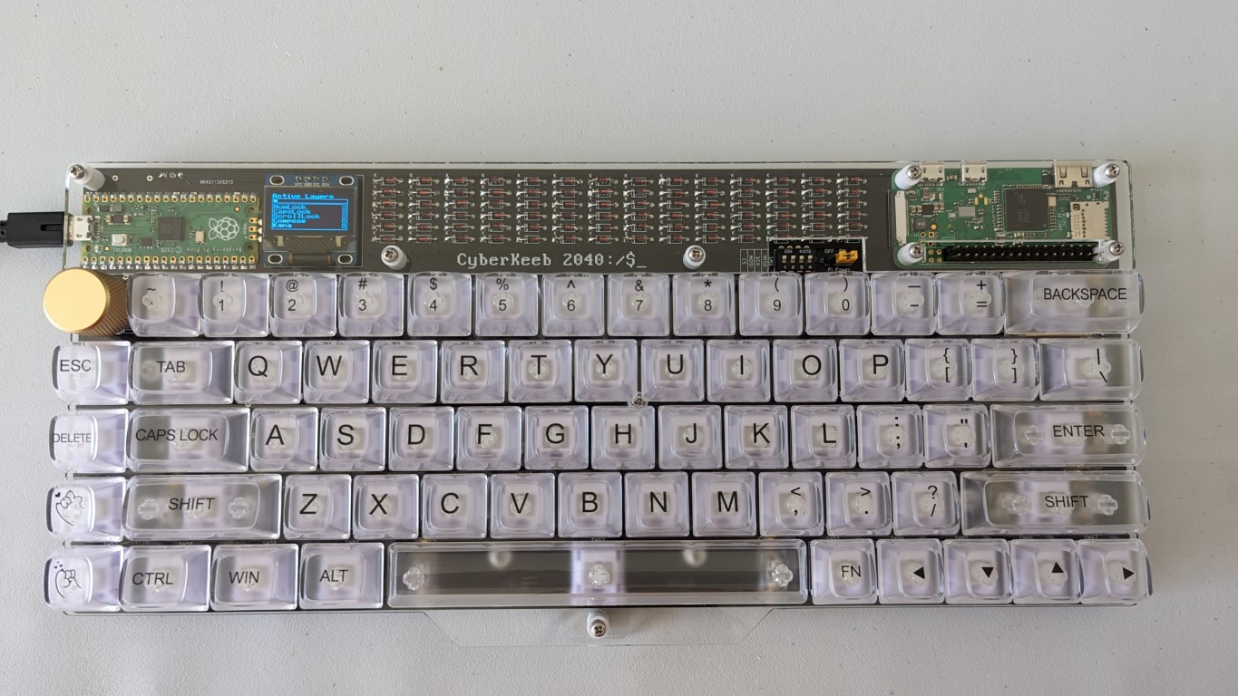
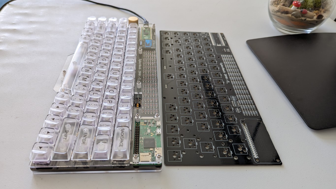
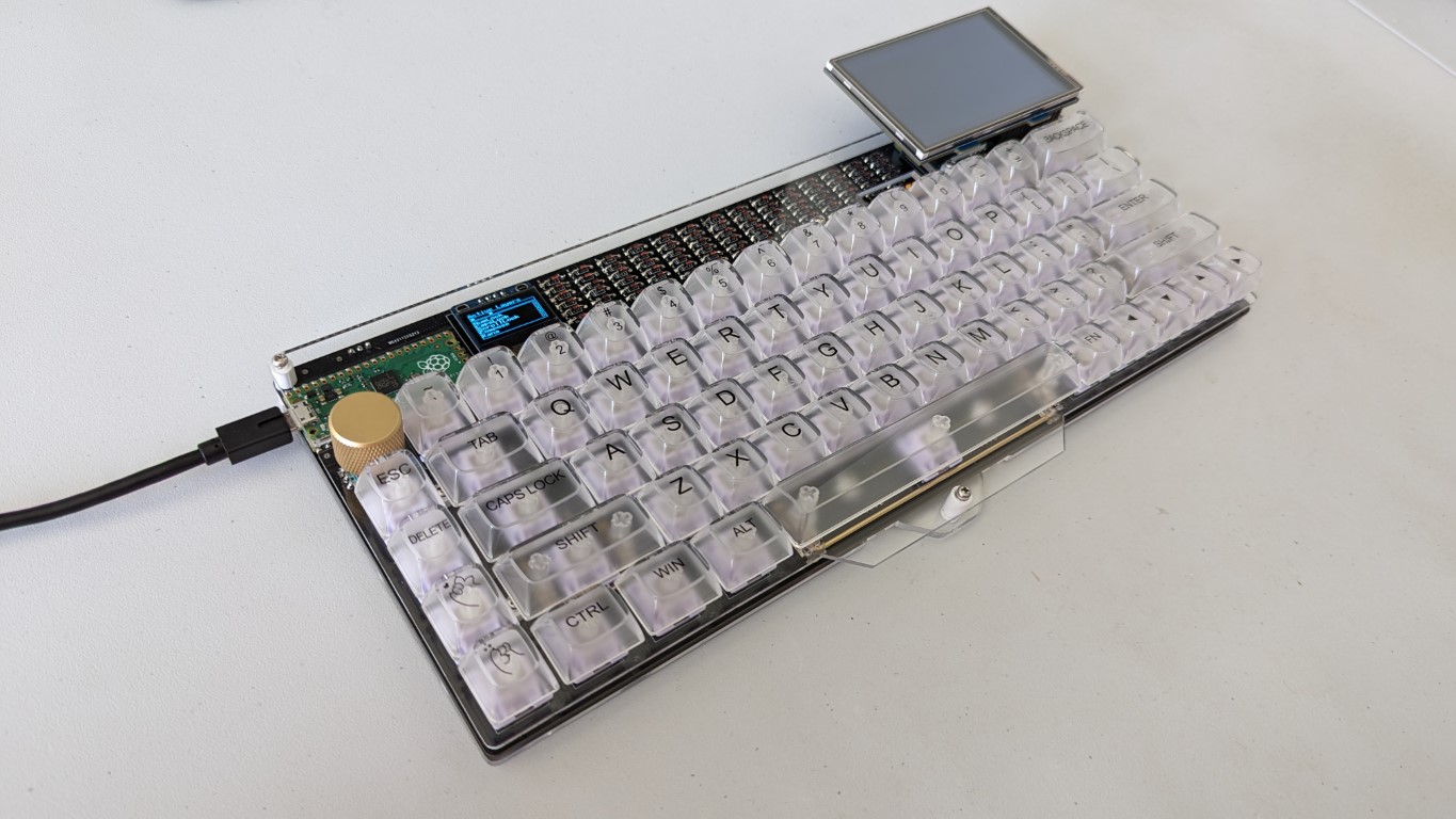
Special thanks to icon-oclast for asking these great questions.
What are the dip switches used for? Is there a recommended default setting for these?
The 4 positions are for each line of the SPI connection between the pi pico and pi zero. This allows cutting the connections between pi pico and pi zero without cutting the power connections. I initially designed it for the (paranoid) scenario where I can't kill the pi zero, but doesn't want it to do autotype or receiving the key strokes, but I found such scenario increasing unlikely. So, if you don't want to solder the DIP switches, feel free to just short the corresponding pins.
Presumably the switch/jumper labeled "pi power" controls pass-through power from the Pico to the Zero?
Yes.
Is there a minimum USB current needed when powering both boards
I don't have the empirical measurements, but here's the estimate: Pico: <20mA. Data source: https://mjoldfield.com/atelier/2021/11/pico-power.html SSD1306: <7mA. Data source: https://hsel.co.uk/2018/12/04/ssd1306-power-consumption/ Pi Zero W: <400mA under stress. Data source: https://www.tomshardware.com/reviews/raspberry-pi-zero-2-w-review Pi Zero 2 W: <600mA under stress.
So let's say it's 700mA if you want to stress the pi zero. I did run the stressberry on pi zero 2 w, with the display hat, and a wireless mouse receiver. The board is connected to the USB3.0 port and there's no under voltage warning, and no visible heat up on the cable or the connectors. However, due to differences on the motherboards, YMMY. I currently don't have a USB power meter to measure the actual current drawn.
Is there a maximum safe current to pass-through (when using the optional display hat for example)?
The trace between pico and pi zero has width of 1mm, and length around 300mm. Assuming you're using 1oz copper thickness, it should result in a maximum current of 1.2 A for temperature rise of 10 degree C.
Is it safe to power the zero independently by setting the pi power switch/jumper to off?
Yes.
What about the two connectors at the bottom of the board, either 4-pin jst sockets as in the build instructions, or possibly 5-pin headers on some revisions of the pcb, how are they intended to be used?
They are for my future plans :) Essentially, they expose three buttons from the key scan matrix, and pin 26 and 27. Pin 26 and 27 are analog input pins and I2C 1. I'm planning to create a plugin module for the joystick mouse pad similar to the one I have on the Pico-Keyboard, and an I2C expansion board for more modules like a num pad.
What cool things can we do if we include the optional 90 degree pin header(s)?
The pin header under the small screen has been removed, because I figured it'll be difficult to use it for anything without creating a giant mess in the firmware. The other header exposes the addressable LEDs. Only WS2812 is supported and tested because it's used in the Pico-Keyboard. However, you might be able to use for other things as it's essentially a GPIO pin with ground and 5V, and a 330 ohm resister on the GPIO pin.
This work is licensed under a Creative Commons Attribution-ShareAlike 4.0 International License.

| Qty | Value | Footprint | References |
|---|---|---|---|
| 84 | D | Diode_THT_Custom:D_DO-35_SOD27_P7.62mm_Horizontal | D1, D2, D10, D11, D12, D13, D14, D15, D16, D17, D18, D19, D20, D21, D22, D23 +68 |
| 4 | 10k | CustomResitor:R_Axial_DIN0207_L6.3mm_D2.5mm_P10.16mm_Horizontal_0402 | R2, R3, R4, R5 |
| 2 | 0.01 μF | CustomCapacitor:C_1206_3216Metric_Pad1.33x1.80mm_HandSolder | C1, locked |
| 1 | 330 | CustomResitor:R_Axial_DIN0207_L6.3mm_D2.5mm_P10.16mm_Horizontal_0603 | R1 |
| 1 | Extra_Keys | Connector_PinSocket_2.54mm:PinSocket_1x05_P2.54mm_Horizontal | J4 |
| 1 | JMD0.96C | JMD0.96C:JMD0.96C | J2 |
| 1 | JoyStick_Or_I2C1 | Connector_PinSocket_2.54mm:PinSocket_1x05_P2.54mm_Horizontal | J5 |
| 1 | PiPowerSwitch | Connector_PinHeader_2.54mm:PinHeader_1x03_P2.54mm_Vertical | SW1 |
| 1 | Pi_Zero | PiZero:Raspberry_Pi_Zero_Socketed_THT_MountingHoles_Castellated | J1 |
| 1 | Pico | MCU_RaspberryPi_and_Boards:RPi_Pico_SMD_TH | U1 |
| 1 | RotaryEncoder_Switch | RotaryEncoder:RotaryEncoder_Alps_EC11E-Switch_Vertical_H20mm_CircularMountingHoles | SW3 |
| 1 | SPI_SW | Button_Switch_THT:SW_DIP_SPSTx04_Slide_6.7x11.72mm_W7.62mm_P2.54mm_LowProfile | SW2 |
| 1 | SW_' | HotswapFix:SW_Hotswap_Kailh_MX_1.00u | SW42 |
| 1 | SW_+ | HotswapFix:SW_Hotswap_Kailh_MX_1.00u | SW16 |
| 1 | SW_, | HotswapFix:SW_Hotswap_Kailh_MX_1.00u | SW52 |
| 1 | SW_- | HotswapFix:SW_Hotswap_Kailh_MX_1.00u | SW15 |
| 1 | SW_. | HotswapFix:SW_Hotswap_Kailh_MX_1.00u | SW53 |
| 1 | SW_/ | HotswapFix:SW_Hotswap_Kailh_MX_1.00u | SW54 |
| 1 | SW_0 | HotswapFix:SW_Hotswap_Kailh_MX_1.00u | SW14 |
| 1 | SW_1 | HotswapFix:SW_Hotswap_Kailh_MX_1.00u | SW5 |
| 1 | SW_2 | HotswapFix:SW_Hotswap_Kailh_MX_1.00u | SW6 |
| 1 | SW_3 | HotswapFix:SW_Hotswap_Kailh_MX_1.00u | SW7 |
| 1 | SW_4 | HotswapFix:SW_Hotswap_Kailh_MX_1.00u | SW8 |
| 1 | SW_5 | HotswapFix:SW_Hotswap_Kailh_MX_1.00u | SW9 |
| 1 | SW_6 | HotswapFix:SW_Hotswap_Kailh_MX_1.00u | SW10 |
| 1 | SW_7 | HotswapFix:SW_Hotswap_Kailh_MX_1.00u | SW11 |
| 1 | SW_8 | HotswapFix:SW_Hotswap_Kailh_MX_1.00u | SW12 |
| 1 | SW_9 | HotswapFix:SW_Hotswap_Kailh_MX_1.00u | SW13 |
| 1 | SW_; | HotswapFix:SW_Hotswap_Kailh_MX_1.00u | SW41 |
| 1 | SW_[ | HotswapFix:SW_Hotswap_Kailh_MX_1.00u | SW29 |
| 1 | SW_] | HotswapFix:SW_Hotswap_Kailh_MX_1.00u | SW43 |
| 1 | SW_` | HotswapFix:SW_Hotswap_Kailh_MX_1.00u | SW4 |
| 1 | SW_a | HotswapFix:SW_Hotswap_Kailh_MX_1.00u | SW33 |
| 1 | SW_alt | HotswapFix:SW_Hotswap_Kailh_MX_1.25u | SW60 |
| 1 | SW_b | HotswapFix:SW_Hotswap_Kailh_MX_1.00u | SW49 |
| 1 | SW_back | HotswapFix:SW_Hotswap_Kailh_MX_2.00u | SW30 |
| 1 | SW_bkslash | HotswapFix:SW_Hotswap_Kailh_MX_1.50u | SW56 |
| 1 | SW_c | HotswapFix:SW_Hotswap_Kailh_MX_1.00u | SW61 |
| 1 | SW_caps | HotswapFix:SW_Hotswap_Kailh_MX_1.75u | SW32 |
| 1 | SW_ctrl | HotswapFix:SW_Hotswap_Kailh_MX_1.25u | SW58 |
| 1 | SW_d | HotswapFix:SW_Hotswap_Kailh_MX_1.00u | SW62 |
| 1 | SW_del | HotswapFix:SW_Hotswap_Kailh_MX_1.00u | SW31 |
| 1 | SW_down | HotswapFix:SW_Hotswap_Kailh_MX_1.00u | SW66 |
| 1 | SW_e | HotswapFix:SW_Hotswap_Kailh_MX_1.00u | SW21 |
| 1 | SW_enter | HotswapFix:SW_Hotswap_Kailh_MX_2.25u | SW69 |
| 1 | SW_esc | HotswapFix:SW_Hotswap_Kailh_MX_1.00u | SW17 |
| 1 | SW_f | HotswapFix:SW_Hotswap_Kailh_MX_1.00u | SW35 |
| 1 | SW_fn1 | HotswapFix:SW_Hotswap_Kailh_MX_1.00u | SW57 |
| 1 | SW_fn2 | HotswapFix:SW_Hotswap_Kailh_MX_1.00u | SW64 |
| 1 | SW_g | HotswapFix:SW_Hotswap_Kailh_MX_1.00u | SW36 |
| 1 | SW_h | HotswapFix:SW_Hotswap_Kailh_MX_1.00u | SW37 |
| 1 | SW_i | HotswapFix:SW_Hotswap_Kailh_MX_1.00u | SW26 |
| 1 | SW_ins | HotswapFix:SW_Hotswap_Kailh_MX_1.00u | SW44 |
| 1 | SW_j | HotswapFix:SW_Hotswap_Kailh_MX_1.00u | SW38 |
| 1 | SW_k | HotswapFix:SW_Hotswap_Kailh_MX_1.00u | SW39 |
| 1 | SW_l | HotswapFix:SW_Hotswap_Kailh_MX_1.00u | SW40 |
| 1 | SW_left | HotswapFix:SW_Hotswap_Kailh_MX_1.00u | SW65 |
| 1 | SW_m | HotswapFix:SW_Hotswap_Kailh_MX_1.00u | SW51 |
| 1 | SW_n | HotswapFix:SW_Hotswap_Kailh_MX_1.00u | SW50 |
| 1 | SW_o | HotswapFix:SW_Hotswap_Kailh_MX_1.00u | SW27 |
| 1 | SW_p | HotswapFix:SW_Hotswap_Kailh_MX_1.00u | SW28 |
| 1 | SW_q | HotswapFix:SW_Hotswap_Kailh_MX_1.00u | SW19 |
| 1 | SW_r | HotswapFix:SW_Hotswap_Kailh_MX_1.00u | SW22 |
| 1 | SW_r_shift | HotswapFix:SW_Hotswap_Kailh_MX_2.75u | SW55 |
| 1 | SW_right | HotswapFix:SW_Hotswap_Kailh_MX_1.00u | SW68 |
| 1 | SW_s | HotswapFix:SW_Hotswap_Kailh_MX_1.00u | SW34 |
| 1 | SW_shift | HotswapFix:SW_Hotswap_Kailh_MX_2.25u | SW45 |
| 1 | SW_space | HotswapFix:SW_Hotswap_Kailh_MX_6.25u | SW63 |
| 1 | SW_super | HotswapFix:SW_Hotswap_Kailh_MX_1.25u | SW59 |
| 1 | SW_t | HotswapFix:SW_Hotswap_Kailh_MX_1.00u | SW23 |
| 1 | SW_tab | HotswapFix:SW_Hotswap_Kailh_MX_1.50u | SW18 |
| 1 | SW_u | HotswapFix:SW_Hotswap_Kailh_MX_1.00u | SW25 |
| 1 | SW_up | HotswapFix:SW_Hotswap_Kailh_MX_1.00u | SW67 |
| 1 | SW_v | HotswapFix:SW_Hotswap_Kailh_MX_1.00u | SW48 |
| 1 | SW_w | HotswapFix:SW_Hotswap_Kailh_MX_1.00u | SW20 |
| 1 | SW_x | HotswapFix:SW_Hotswap_Kailh_MX_1.00u | SW47 |
| 1 | SW_y | HotswapFix:SW_Hotswap_Kailh_MX_1.00u | SW24 |
| 1 | SW_z | HotswapFix:SW_Hotswap_Kailh_MX_1.00u | SW46 |
| 1 | WS2812 | Connector_PinHeader_2.54mm:PinHeader_1x03_P2.54mm_Vertical | J3 |
The 166 most common of 182 parts.
ryomuk/TangNanoDCJ11MEM
Memory system and UART implemented on Tang Nano 20K for DEC DCJ11 PDP-11 Processor


cherry-embedded/HSCanT-hardware
HSCanT is a USB to 4-channel CAN FD tool designed based on the HPM5321 chip.

Duckle29/Vitamins-included
This repo holds a variation of the lets split. This board requires no soldering


VIPQualityPost/easy-esc-stm32f103-mt6701-ncp81155
small, closed loop simpleFOC driver board, that can be assembled for <$10 with mostly basic components at LCSC. has support for current sensing and mounting WS2812 RGBLED for indicating, as well as USB C for serial…
It measures 308.8 × 130.3 mm and has 2 copper layers, 1.6 mm thick.
182 parts, built around the WS2812. The full list of its parts is on this page, with links to each part's symbol and footprint where PCBKit's library has them.
From the zli117/CyberKeeb2040 repository on GitHub, at the commit this page was made from: the board is PCB/MainBoard/MainBoard.kicad_pcb and its schematic PCB/MainBoard/MainBoard.kicad_sch. PCBKit opens the board in the browser, with nothing to install.
Its repository publishes it under the CC-BY-SA-4.0 licence: you may reuse it on that licence's terms (keep the author's notice, and for a copyleft licence share your changes alike).