

4 layers240 × 107 mm

 na103/BigBlue3
Reverse engineering of Hardital Zorro Big Blue
ZBB B is an open-source printed circuit board by na103, from the na103/BigBlue repository on GitHub. It is a 4-layer board of 344 × 69 mm with 139 parts on 302 nets, routed with 2,926 tracks and 50 vias.
It is built around the 74LS32SC. Its parts include 104 capacitors, 11 connectors, 3 ICs and 2 resistors. It belongs with the FPGA and CPLD boards of this library.
Reverse engineering of Hardital Zorro Big Blue, an Italian Amiga expansion produced in the late 1980s.
The Zorro Big Blue was an external metal cabinet (roughly 46×37×15 cm) that gave Amiga 500 owners — and Amiga 1000 owners, possibly with some modifications — the expansion capabilities normally reserved for the Amiga 2000. It connected to the host through the 86-pin side expansion connector and provided a backplane with three Zorro II slots and three ISA slots, plus drive bays for 3.5" and 5.25" floppies, a hard disk bay, a cooling fan, and a 40W power supply.
The ISA slots could not host PC cards directly from the Amiga side: they were usable only in combination with an x86 bridgeboard installed in the system, and the ISA cards remained accessible only to the PC side of that setup. The name "Big Blue" refers to this PC-compatibility angle ("Big Blue" being IBM's nickname).
At the time of The Games Machine review ( by Carlo Santagostino November 1989), the system retailed for 180,000 Italian Lire for the backplane plus 150,000 Lire for the chassis, a competitive alternative to buying a full Amiga 2000.


Reverse engineering of the programmable logic on the system, distributed across two interconnected boards:
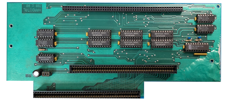
Board A — host interface and transceiver steering between the host Amiga and the backplane
Board B — Zorro II backplane carrying the three slots, with bus arbitration, address decoding, and Amiga collision detection
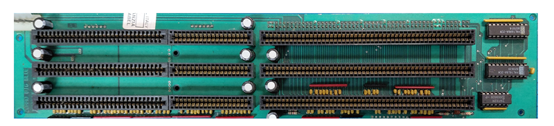
The two PAL16L8 chips (steering on Board A, collision detection on Board B) were fully extracted using DuPAL and reimplemented as documented GAL16V8 replacements with annotated CUPL sources. Minor differences between the original PALs and their GAL replacements — tri-state behavior, product term limits, polarity conventions — are noted in the source files.
The PAL16R8 used for Zorro bus arbitration (on Board B) was not fully decoded: DuPAL doesn't reliably handle registered outputs (the state space requires specific clock sequences that brute-force extraction can't fully explore). Its equations were instead reconstructed by comparing the chip's response to the Peeper with the schematics of the early Amiga 2000 revision, which uses a functionally similar arbitration block.
The repository includes:
The unit examined for this reverse engineering shows several signs that suggest it is not a final production board but rather a prototype or a pre-production revision:
Whether these are factory choices in a cost-reduced design, leftover modifications from a pre-production prototype, or later field hacks by a previous owner is impossible to say with certainty without comparing against other surviving units. The reverse engineering documented here describes the board as found, with notes where the original design intent can be reasonably inferred.
The reverse-engineered logic has been validated on real hardware in its period-correct configuration: Amiga 500 + Kickstart 1.3 + Zorro II memory expansion. In this setup the system boots and operates, with all three Zorro II slots functional for passive cards (RAM, I/O).
A few limitations emerged during testing and are worth documenting:
In short: the Big Blue is fully functional for its intended use case (light expansion of an A500 with period-correct software), and the limitations are inherent to its 1989 design philosophy rather than to faults in the hardware.
A big thank you to Carlo Santagostino for providing HARDITAL Zorro BigBlue and historical memory
If you found this my work useful, please consider buying me a cup of coffee if you want:

This work is licensed under a Creative Commons Attribution 4.0 International License. See https://creativecommons.org/licenses/by/4.0/.
| Qty | Value | Footprint | References |
|---|---|---|---|
| 91 | 1nF | Amiga_Library:C_Rect_L4.6mm_W2.0mm_P2.50mm_MKS02_FKP02 | C10, C11, C12, C13, C14, C15, C16, C17, C18, C19, C20, C21, C22, C100, C101, C102 +75 |
| 8 | 100uF | Amiga_Library:CP_Radial_D8.0mm_P3.80mm | C1, C2, C4, C5, C28, C29, C30, C60 |
| 8 | 1K | Amiga_Library:R_Array_SIP10 | RN5, RN7, RN9, RN10, RN11, RN12, RN14, RN15 |
| 7 | 1K | Amiga_Library:R_Array_SIP6 | RN3, RN6, RN8, RN13, RN16, RN17, RN18 |
| 3 | 100nF | Amiga_Library:C_Rect_L4.6mm_W2.0mm_P2.50mm_MKS02_FKP02 | C3, C103, C104 |
| 3 | ISA_16_Bit_Extended | Amiga_Library:ISA 16 Bit | J5, J6, J7 |
| 3 | ISA_8_Bit | Amiga_Library:ISA 8 Bit | J8, J9, J10 |
| 3 | Zorro-II | Amiga_Library:Zorro-II | J2, J3, J4 |
| 2 | 10K | Amiga_Library:R_Array_SIP8 | RN1, RN2 |
| 2 | 1K | Amiga_Library:R_Axial_DIN0207_L6.3mm_D2.5mm_P7.62mm_Horizontal | R1, R2 |
| 2 | ATF16V8Bxx-xxPU | Package_DIP:DIP-20_W7.62mm | U1, U2 |
| 1 | 100uF 25V | Amiga_Library:CP_Radial_D8.0mm_P3.80mm | C6 |
| 1 | 1K | Amiga_Library:R_Array_SIP8 | RN4 |
| 1 | 1nFC | Amiga_Library:C_Rect_L4.6mm_W2.0mm_P2.50mm_MKS02_FKP02 | C27 |
| 1 | 640901-3 | Connector_Molex:Molex_SPOX_5267-05A_1x05_P2.50mm_Vertical | CN1 |
| 1 | 74LS32 | Package_DIP:DIP-14_W7.62mm | U3 |
| 1 | EXPANSION_SLOT | Amiga_Library:PinHeader_2x52_P2.54mm_Vertical | J1 |
| 1 | SolderJumper_2_Bridged | Jumper:SolderJumper-2_P1.3mm_Bridged_RoundedPad1.0x1.5mm | JP1 |


jes/scamp-cpu
A homebrew 16-bit CPU with a homebrew Unix-like-ish operating system.

mudmin/AnotherMaker
This is where I will store code snippets for AnotherMaker Videos


The-Invent0r/8-bit-Computer-PCB
These are the KiCAD files for my 8-Bit Computer.

tjboldt/Apple2-IO-RPi
Apple II expansion card using a Raspberry Pi for I/O
It measures 344 × 69 mm and has 4 copper layers, 1.6 mm thick.
139 parts, built around the 74LS32SC. The full list of its parts is on this page, with links to each part's symbol and footprint where PCBKit's library has them.
From the na103/BigBlue repository on GitHub, at the commit this page was made from: the board is Kicad/ZBB_B/ZBB_B.kicad_pcb and its schematic Kicad/ZBB_A/ZBB_A.kicad_sch. PCBKit opens the board in the browser, with nothing to install.
Its repository states no licence, so its author keeps all rights: ask na103 before reusing the design.