
2 layers58.1 × 41.8 mm
Esp32-led matrix
n2048-creative-technology/esp32-led-matrix
double sided 8x8 addressable led matrix with integrated esp32-c3 module
147 parts

ESP32 board , powered by USB-C, controlls 5V addressable LEDs via pin header
Esp32-c3-led is an open-source printed circuit board by n2048-creative-technology, from the n2048-creative-technology/esp32-c3-led-controller repository on GitHub. It is a 2-layer board of 20.5 × 35.5 mm with 20 parts on 35 nets, routed with 151 tracks and 15 vias.
It is built around the ESP32-C6-WROOM-1-N8, LM1117DT-3.3 and USBLC6-2SC6. Its parts include 6 capacitors, 5 resistors, 3 ICs, 3 connectors and 2 diodes. It belongs with the ESP32 and RISC-V boards of this library.


A compact 2-layer PCB built around the ESP32-C6-WROOM-1 module, providing USB-C power/programming, on-board 3.3V regulation, ESD-protected USB data lines, a reset button, and an addressable/status LED header. All electronic parts are sourced against JLCPCB's live parts catalog for turnkey assembly.
| Top side (regulator / passives) | Bottom side (ESP32 module / USB-C) |
|---|---|
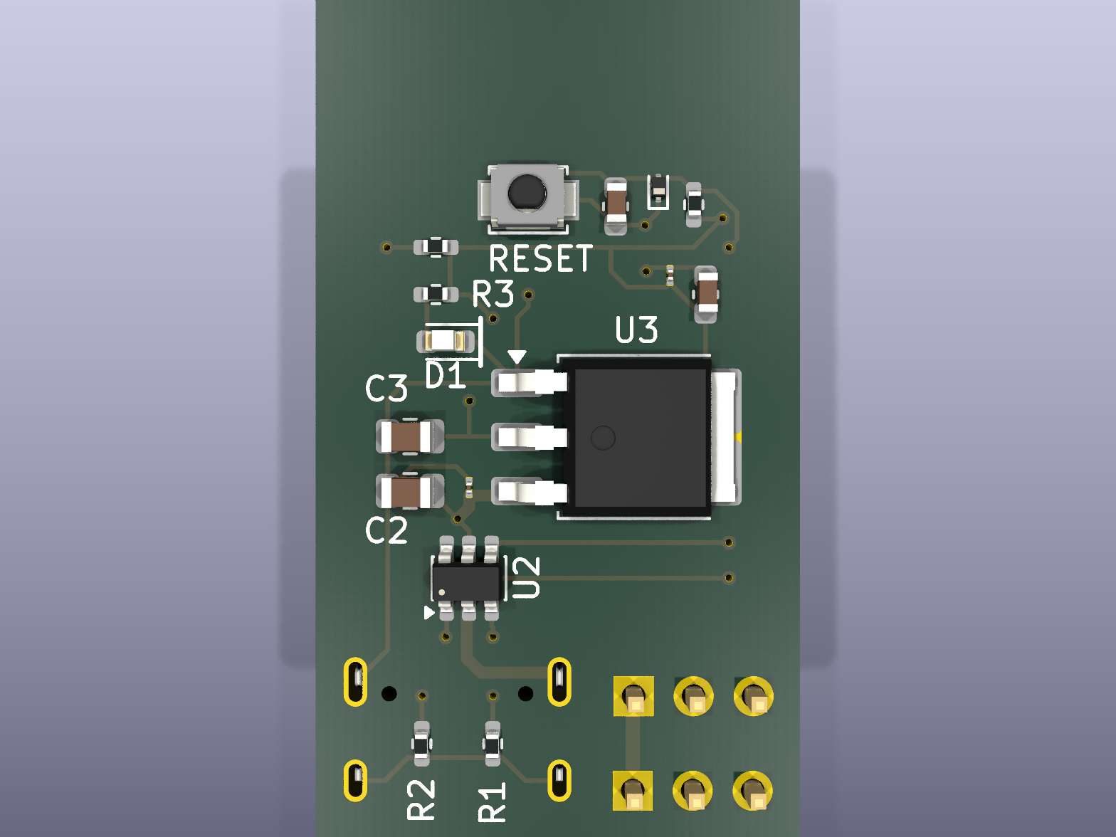 | 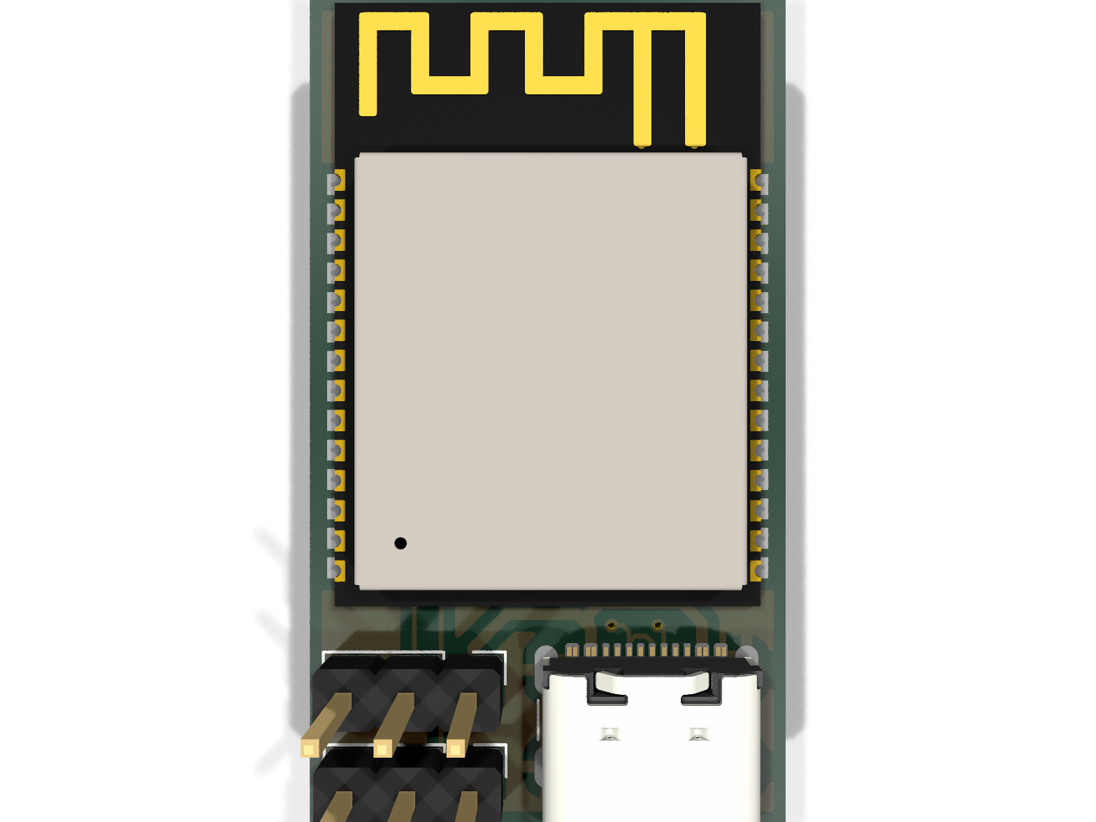 |
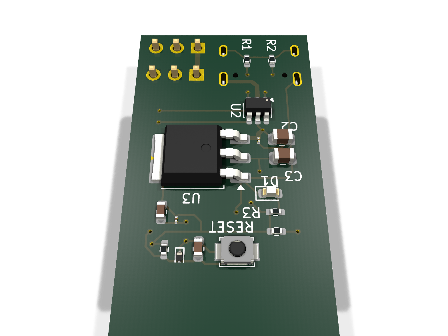
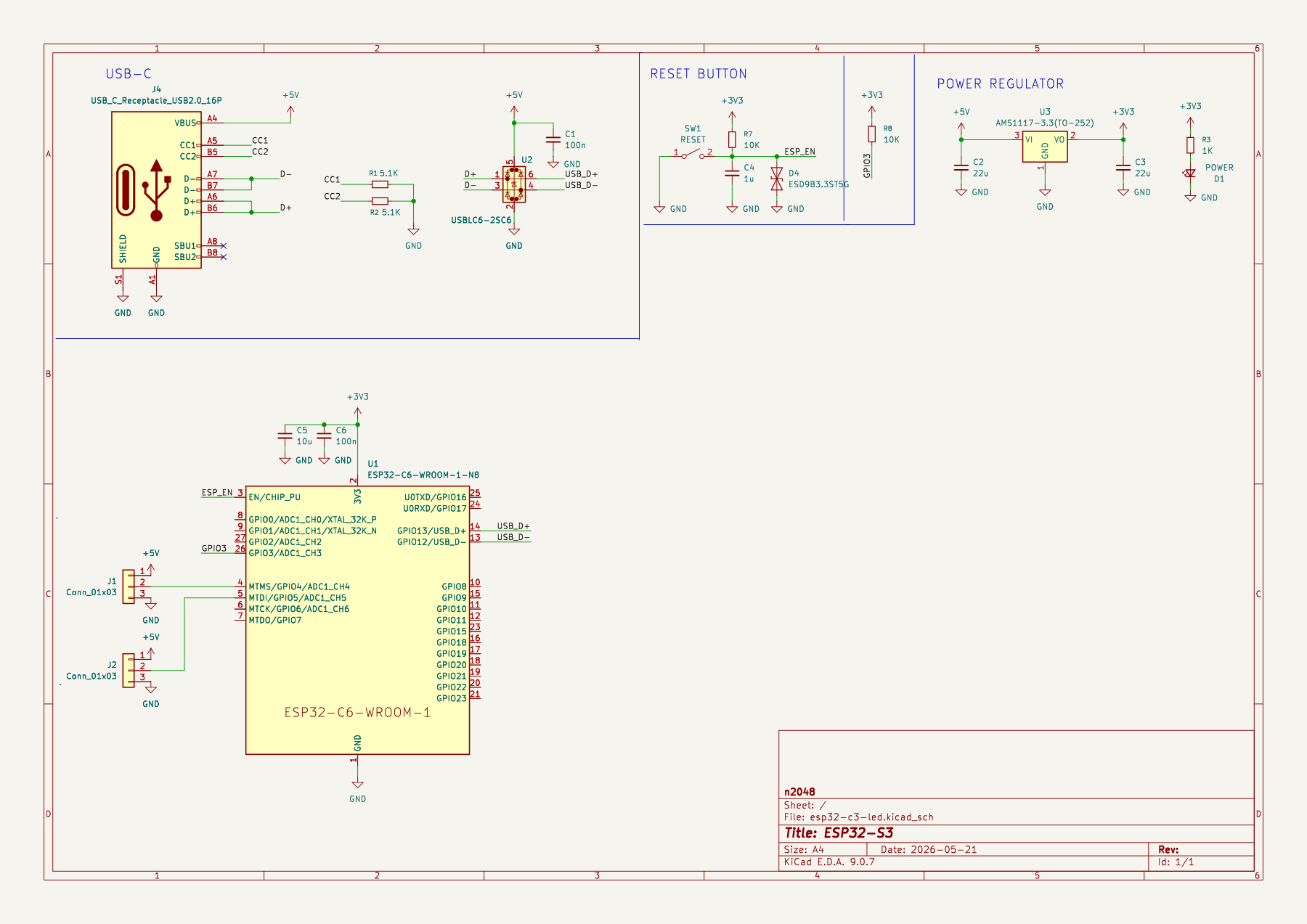
Full-resolution vector version: docs/images/schematic.pdf
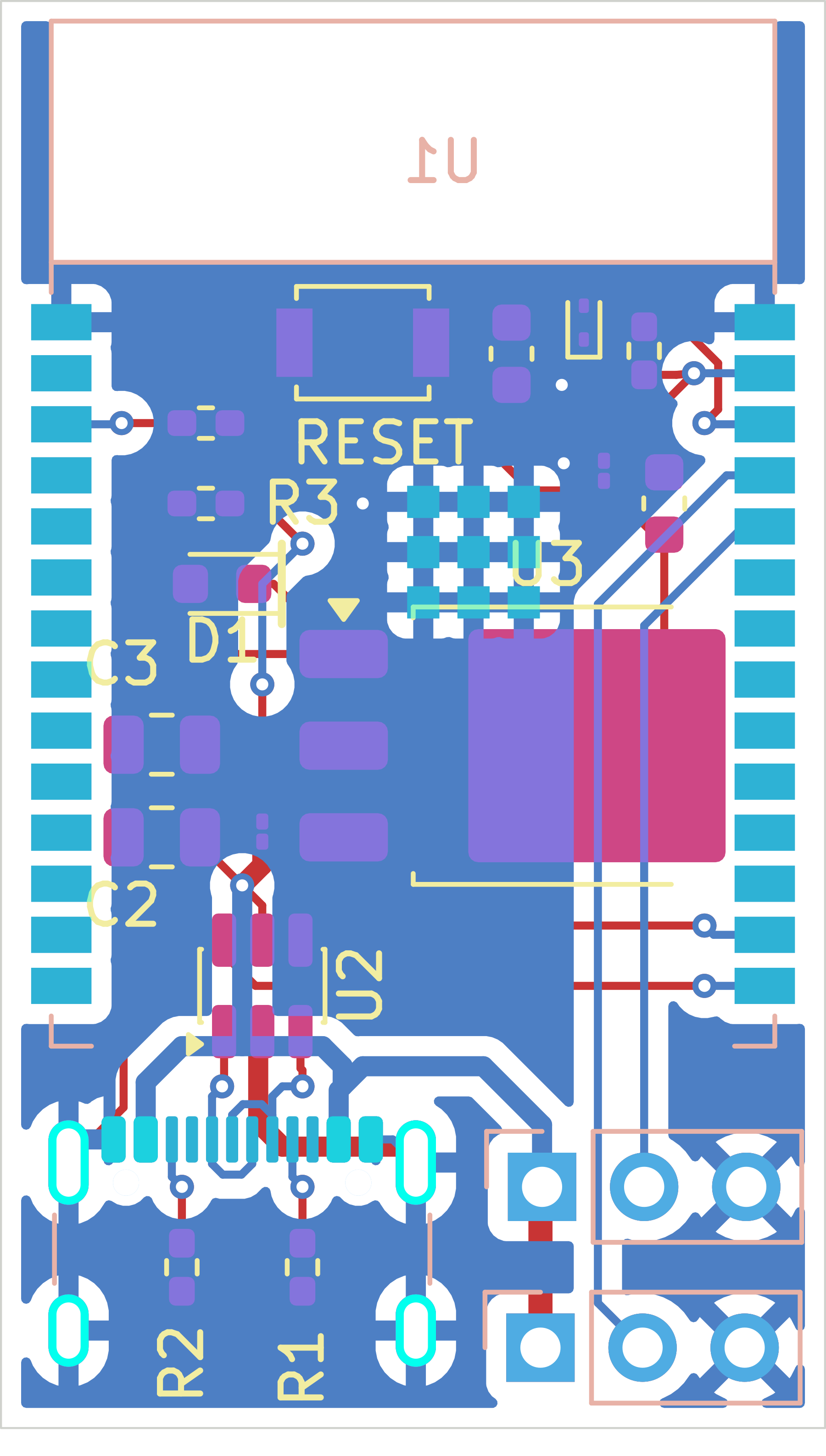
Copper (F.Cu / B.Cu), silkscreen, and solder mask layers, board outline shown.
All parts verified against the live JLCPCB Open Platform API (real-time stock/pricing).
Full machine-readable BOM: BOM_jlcpcb_verified.csv
| Ref | Part | LCSC # | Library |
|---|---|---|---|
| U1 | ESP32-C6-WROOM-1-N8 | C5366877 | Extended |
| U2 | USBLC6-2SC6-FS | C6807798 | Extended |
| U3 | AMS1117-3.3(TO-252) | C41347676 | Extended |
| D1 | KT-0603R (red LED) | C2286 | Basic |
| D4 | ESD9B3.3ST5G | C96512 | Extended |
| SW1 | B3U-1000P (tactile switch) | C231329 | Extended |
| J1, J2 | HX PH254-01-03-Z-L11.5 (1×3 header) | C52016391 | Extended |
| J4 | USB4105-GF-A (USB-C receptacle, 16P) | C3020560 | Extended |
| R1, R2 | 5.1kΩ 0402 | C25905 | Basic |
| R3 | 1kΩ 0402 | C11702 | Basic |
| R7, R8 | 10kΩ 0402 | C25744 | Basic |
| C1, C6 | 100nF 01005 | C307376 | Extended |
| C2, C3 | 22µF 0805 | C129302 | Extended |
| C4 | 1µF 0603 | C15849 | Basic |
| C5 | 10µF 0603 | C7472959 | Extended |
Board is set up for JLCPCB fabrication + assembly out of the box.
production/ contains regenerated, verified fabrication files:
esp32-c3-led_gerbers.zip — Gerbers + Excellon drill file (upload
directly to JLCPCB's PCB order)bom.csv — JLCPCB-format BOM with a populated LCSC Part # column
for every line (Comment / Designator / Footprint / LCSC Part #);
each part number is a live, in-stock JLCPCB catalog matchpositions.csv — CPL / pick-and-place file (Ref, Val, Package,
PosX, PosY, Rot, Side), regenerated from the current board so
bottom-side parts (J1, J2, J4, U1) are correctly marked bottomesp32-c3-led.kicad_pro / .kicad_sch / .kicad_pcb remain the
authoritative KiCad 9 source files; every part also carries LCSC and
MPN custom fields on its schematic symbol.
Note: an earlier BOM/CPL pair generated by the Fabrication Toolkit KiCad plugin shipped with an empty
LCSC Part #column, which caused JLCPCB's auto-matcher to select wrong/out-of-stock substitutes and fail to match the connectors (J1/J2/J4) entirely. The files above were regenerated directly from the schematic's verified LCSC data and confirmed against the live JLCPCB API — use these instead of re-running the plugin unless the design changes.
Verified clean via kicad-cli pcb drc: only 3 benign warnings remain
(lib_footprint_mismatch on C1/C6/D1, confirming intentional local
customizations — see below). No copper clearance errors, no
dangling/floating silkscreen text, no component placement changes.
To avoid JLCPCB assembly clarification requests, every part with a genuine orientation dependency has an unambiguous silkscreen or Gerber-encoded marker:
esp32-c3-led.kicad_pro      KiCad project
esp32-c3-led.kicad_sch      Schematic
esp32-c3-led.kicad_pcb      PCB layout
BOM_jlcpcb_verified.csv     Reference BOM with LCSC part numbers (grouped by value)
docs/images/                Renders and diagrams (this README)
production/                  JLCPCB-ready fabrication output:
  esp32-c3-led_gerbers.zip     Gerbers + drill (upload as-is)
  bom.csv                      JLCPCB BOM (Comment/Designator/Footprint/LCSC Part #)
  positions.csv                CPL / pick-and-place file
gerbers/ Individual Gerber/drill layer files| Qty | Value | Footprint | References |
|---|---|---|---|
| 2 | 100n | Capacitor_SMD:C_01005_0402Metric | C1, C6 |
| 2 | 10K | Resistor_SMD:R_0402_1005Metric_Pad0.72x0.64mm_HandSolder | R7, R8 |
| 2 | 22u | Capacitor_SMD:C_0805_2012Metric | C2, C3 |
| 2 | 5.1K | Resistor_SMD:R_0402_1005Metric_Pad0.72x0.64mm_HandSolder | R1, R2 |
| 2 | Conn_01x03 | Connector_PinHeader_2.54mm:PinHeader_1x03_P2.54mm_Vertical | J1, J2 |
| 1 | 10u | Capacitor_SMD:C_0603_1608Metric | C5 |
| 1 | 1K | Resistor_SMD:R_0402_1005Metric_Pad0.72x0.64mm_HandSolder | R3 |
| 1 | 1u | Capacitor_SMD:C_0603_1608Metric | C4 |
| 1 | ESD3.3 | Diode_SMD:D_SOD-923 | D4 |
| 1 | ESP32-C6-WROOM-1 | PCM_Espressif:ESP32-C6-WROOM-1 | U1 |
| 1 | LM1117DT-3.3 | Package_TO_SOT_SMD:TO-252-3_TabPin2 | U3 |
| 1 | POWER | LED_SMD:LED_0603_1608Metric | D1 |
| 1 | RESET | Button_Switch_SMD:SW_SPST_B3U-1000P | SW1 |
| 1 | USBLC6-2SC6 | Package_TO_SOT_SMD:SOT-23-6 | U2 |
| 1 | USB_C_Receptacle_USB2.0_16P | Connector_USB:USB_C_Receptacle_GCT_USB4105-xx-A_16P_TopMnt_Horizontal | J4 |
It measures 20.5 × 35.5 mm and has 2 copper layers, 1.6 mm thick.
20 parts, built around the ESP32-C6-WROOM-1-N8, LM1117DT-3.3 and USBLC6-2SC6. The full list of its parts is on this page, with links to each part's symbol and footprint where PCBKit's library has them.
From the n2048-creative-technology/esp32-c3-led-controller repository on GitHub, at the commit this page was made from: the board is esp32-c3-led.kicad_pcb and its schematic esp32-c3-led.kicad_sch. PCBKit opens the board in the browser, with nothing to install.
Its repository states no licence, so its author keeps all rights: ask n2048-creative-technology before reusing the design.
n2048-creative-technology/esp32-led-matrix
double sided 8x8 addressable led matrix with integrated esp32-c3 module

siliconvalleyar-oss/esp32_xiazhi_pcb
Repositorio del diseño PCB para el dispositivo XiaoZhi, una estación de desarrollo y asistente de voz de código abierto basado en el ESP32-C6.

Abean2k/WizServoTester
A servo controller PCB that can control up to 4 servos using onboard controls and a simple web app.

pushtiujeniya/esp32-c6-environmental-logger
This repository contains an Environmental Sensor Station and Data Logger powered by the ESP32-C6-WROOM-1 microcontroller.


jrowe88/ecoport-bridge
CTA-2045 (EcoPort) bridge for a Rinnai REHP65 heat pump water heater

Connicpu/thermostat
DIY Zigbee thermostat (ESP32-C6) with day/night schedule and a Home Assistant Lovelace card

CornetPrisme/PCB-Thermometer
Custom environmental sensor node based on the ESP32-C6 (Wi-Fi 6, BLE 5, Zigbee/Thread). It features three distinct temperature and humidity sensors on a shared I2C bus, is powered via USB-C (3.3V LDO), and includes two…