
2 layers70 × 71 mm
Jewelled lc1
matthiasnowak/jewelled
This is a panel meant for production of the Earrings, allowing for 2 Earrings per panel.
148 parts3

 Myflash911/CH32V
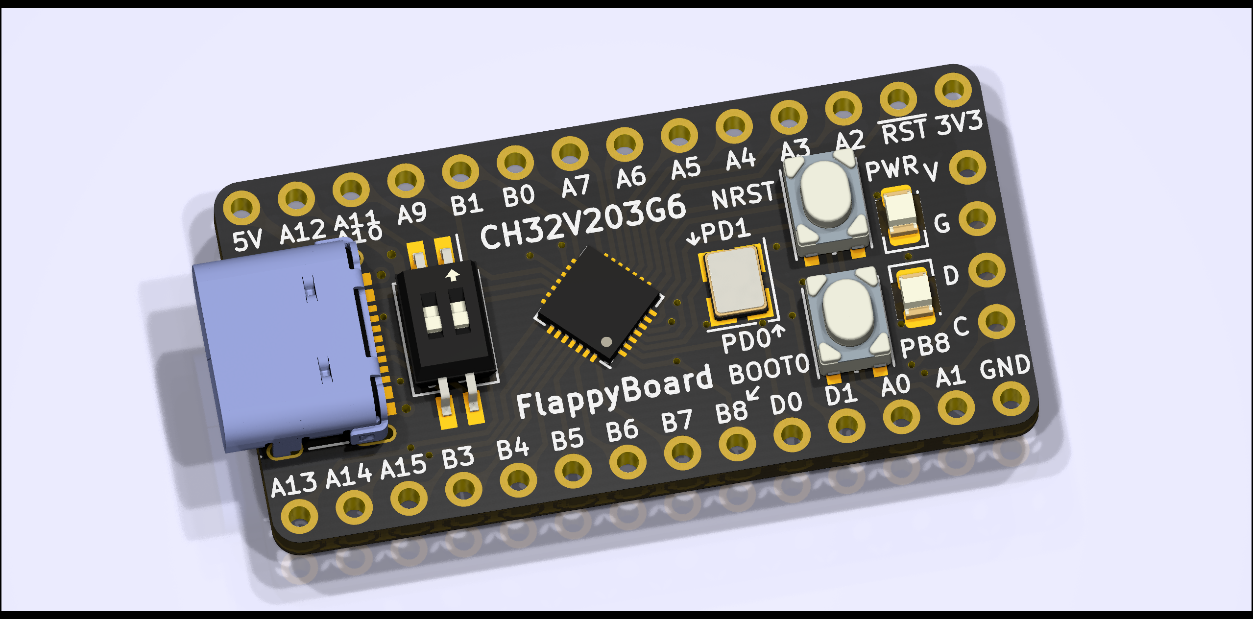
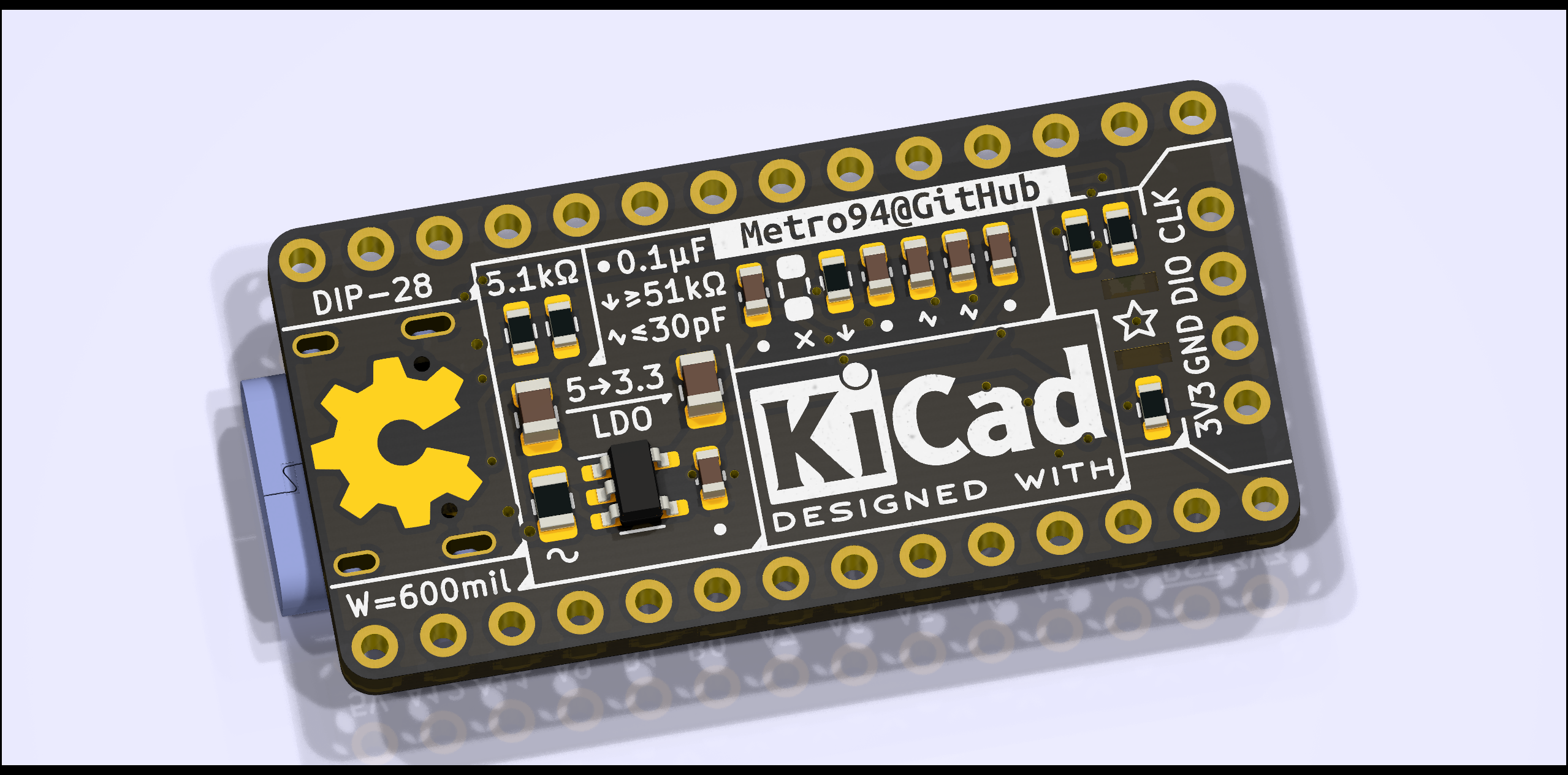
A minimum development board for CH32V203G6. The goal is simplicity, convenience and low-cost.
FlappyBoard is an open-source printed circuit board by Myflash911, from the Myflash911/CH32V repository on GitHub, published under the CERN-OHL-P-2.0 licence. It is a 2-layer board of 17.8 × 35.6 mm with 30 parts on 39 nets, routed with 292 tracks and 26 vias.
It is built around the CH32V203G6U6. Its parts include 8 capacitors, 6 resistors, 4 connectors, 3 switches and 2 ICs. It belongs with the RISC-V boards of this library.
中文 | English
A minimum development board for CH32V203G6. The goal is simplicity, convenience and low-cost.
KiCad 6.0.6
It's simple and convenient to use USB download of WCHISPTool. Also serial download and debug port download is available.
WCHISTool requires correct MCU model (CH32V203) to download. The DIP switch shall be ON for downloading, and power the board with BOOT0 button pushed. If everything goes well, WCHISPTool shall report the MCU.
There are two LEDs on the board, including PWR for power status (3.3V powered) and PB8 for user-defined LED.
There are two buttons on the board, including NRST for system reset and BOOT0 for boot mode (the default is to run user program in Flash, and push button to run bootloader in ROM).
Note: In CH32V203G6, PB8 and BOOT0 is multiplexed. The behavior of this pin is:
- When booting, MCU requires BOOT0 status via this pin, and this pin is input. When BOOT0 button is pushed, the LED of PB8 is lighted to hint.
- After entering user program, the PB8 pin is available for output only, and the input value is invalid. Now, the LED of PB8 can be controlled by user program, but the status of BOOT0 button cannot be read.
CH32V203G6 can accept external oscillator and crystal. The valid frequency range is 3-25MHz.
| Qty | Value | Footprint | References |
|---|---|---|---|
| 4 | 0.1μF | Capacitor_SMD:C_0603_1608Metric | C3, C4, C5, C8 |
| 3 | 1kΩ | Resistor_SMD:R_0603_1608Metric | R4, R5, R6 |
| 2 | 1μF | Capacitor_SMD:C_0805_2012Metric | C1, C2 |
| 2 | 27pF | Capacitor_SMD:C_0603_1608Metric | C6, C7 |
| 2 | 5.1kΩ | Resistor_SMD:R_0603_1608Metric | R1, R2 |
| 2 | Conn_01x14 | Connector_Pin_NoSilkscreen:Pin_1x14_P2.54mm | J2, J3 |
| 2 | SW_Push | Button_Switch_SMD:SW_Push_1P1T_NO_Vertical_Wuerth_434133025816 | SW2, SW3 |
| 1 | 51kΩ | Resistor_SMD:R_0603_1608Metric | R3 |
| 1 | CH32V203G6 | Package_DFN_QFN:QFN-28-1EP_4x4mm_P0.4mm_EP2.3x2.3mm | U2 |
| 1 | Conn_01x04 | Connector_Pin_NoSilkscreen:Pin_1x04_P2.54mm | J4 |
| 1 | Crystal_GND24_Small | Crystal:Crystal_SMD_3225-4Pin_3.2x2.5mm | Y1 |
| 1 | Fuse_Small | Fuse:Fuse_0805_2012Metric | F1 |
| 1 | G*** | kibuzzard-6318E6BD | kibuzzard-6318E6BD |
| 1 | LED_IceBlue | LED_SMD:LED_0805_2012Metric | D1 |
| 1 | LED_Pink | LED_SMD:LED_0805_2012Metric | D2 |
| 1 | SW_DIP_x02 | Button_Switch_SMD:SW_DIP_SPSTx02_Slide_Copal_CHS-02B_W7.62mm_P1.27mm | SW1 |
| 1 | USB_C_Receptacle_USB2.0 | Connector_USB:USB_C_Receptacle_Palconn_UTC16-G | J1 |
| 1 | XC6206B331MR | Package_TO_SOT_SMD:SOT-23-5 | U1 |
The 28 most common of 30 parts.
It measures 17.8 × 35.6 mm and has 2 copper layers, 1.6 mm thick.
30 parts, built around the CH32V203G6U6. The full list of its parts is on this page, with links to each part's symbol and footprint where PCBKit's library has them.
From the Myflash911/CH32V repository on GitHub, at the commit this page was made from: the board is hardware/FlappyBoard.kicad_pcb and its schematic hardware/FlappyBoard.kicad_sch. PCBKit opens the board in the browser, with nothing to install.
Its repository publishes it under the CERN-OHL-P-2.0 licence: you may reuse it on that licence's terms (keep the author's notice, and for a copyleft licence share your changes alike).
matthiasnowak/jewelled
This is a panel meant for production of the Earrings, allowing for 2 Earrings per panel.


buildwithnoknok/module-usb-led
noknok LEDs - USB-controlled 8x WS2812b RGB LED module for the noknok ecosystem

buildwithnoknok/module-usb-led-16x
noknok LEDs 16x - USB-controlled 16x RGBW LED module (round board, CH32V203)
