4 layers24.4 × 24.4 mm
OSO SWAT C1-rounded
joeycastillo/Sensor-Watch
A board replacement for the classic Casio F-91W wristwatch
36 parts2.1k

 mwrnd/OpenCAPI_Breakout3
OpenCAPI Breakout to U.FL/UMCC
OpenCAPI Breakout is an open-source printed circuit board by mwrnd, from the mwrnd/OpenCAPI_Breakout repository on GitHub, published under the BSD-2-Clause licence. It is a 4-layer board of 50 × 71 mm with 36 parts on 49 nets, routed with 1,234 tracks and 280 vias.
It belongs with the interfaces and adapters boards of this library.
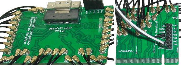
OpenCAPI to U.FL/UMCC Connector breakout.
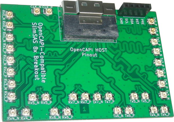
I have successfully tested the board using 3M 8ES8-1DF21(Datasheet) and SlimSAS SFF-8654 8i 85-Ohm(Archived) cables. The 3M Cable has better performance.
No consideration was given to pinout compatibility with the SlimSAS SFF-8654 Standard.
The Open Coherant Accelerator Processor Interface (OpenCAPI) was a standard that had FPGA-based Advanced Accelerated Cable (AAC) Add-In cards such as ADM-PCIE-9H3, ADM-PCIE-9H7, ADM-PCIE-9V3, ADM-PCIE-9V5, BittWare XUPSVH, BittWare XUP-VV4, BittWare XUP-VVH, and Nvidia Innova-2 Flex.
Related Projects: PCIe_x8_Breakout, OpenCAPI-to-PCIe, OpenCAPI-to-PCIe_x4_Host_and_Endpoint, QSFP_Breakout, HDMI_Breakout, SFP_Plug_Breakout
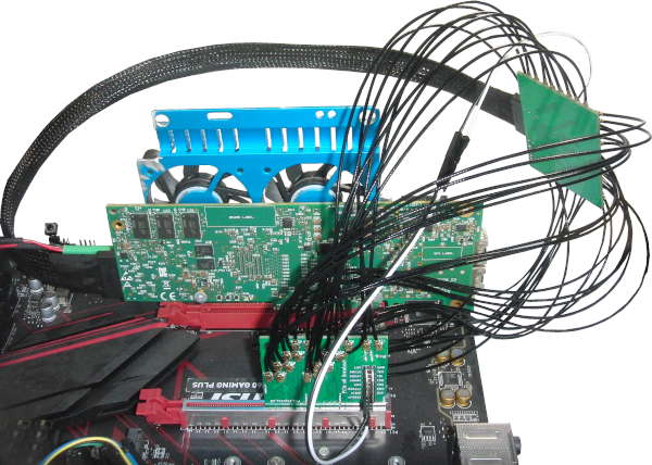
This board can be used along with a PCIe_x8_Breakout board to test OpenCAPI-to-PCIe on the Innova-2 SmartNIC. PCIe 3.0 x4 at 8.0GT/s works. Standard 0.1" M-F Jumpers are used for the PCIe Reset Signal (nPERST) and its GND.
With cables shorter than 100mm~=4" the adapters work. The RX U.FL-to-U.FL cables are all the same length as each other and likewise all TX cables are the same length but RX and TX are different lengths as that is what I had available. RX on the PCIe board connects to RX on the OpenCAPI board as it uses the OpenCAPI Host pinout.
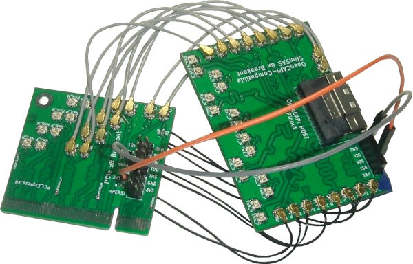
PCIe x4 In-system:
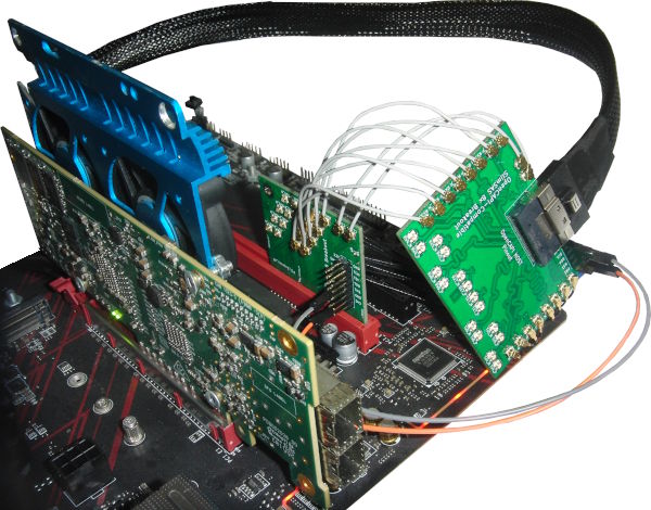
However, using 250mm IPEX cables the adapters fail for PCIe x8:
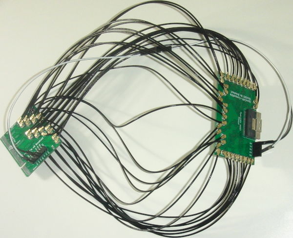
PCIe x8 In-system:
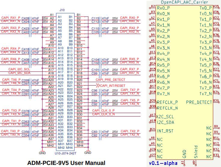
Main difference between the First and Second Revisions is their silkscreen labelling. Both are based on the pinout from the ADM-PCIE-9V5 User Manual (Pg15-19of38).
The First Revision uses the OpenCAPI Host pinout which is the row A-to-B/B-to-A swapped version of the Carrier pinout that is used on OpenCAPI AAC Add-In cards. When used with a PCIe_x8_Breakout Rx signals connect to Rx and Tx to Tx.
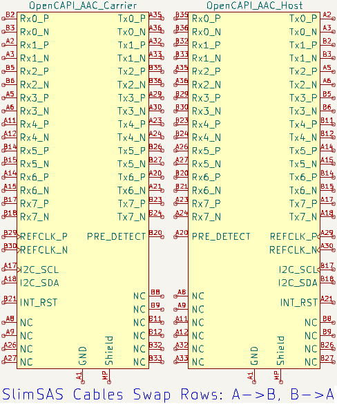
Labels are relative to the Host. Host RX is Carrier TX and vice versa so the Rx pins on this board have transmitter signals from the Add-in card on them. Tx pins connect to the Add-in card's receiver signals.
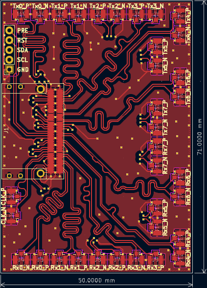
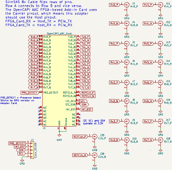
The Second Revision changes the silkscreen to label the U.FL connectors with the signal that is on them. Tx pins connect to the Add-In card's transmitter pins and Rx signals connect to receiver pins.
The board also annotates the corresponding GTY channels when connected to an MNV303212A Rev.A2 board. The MNV303212A's swapped differential pairs are also annotated.
When used with a PCIe_x8_Breakout Rx signals connect to PCIe Tx and Tx to Rx.
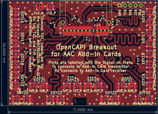
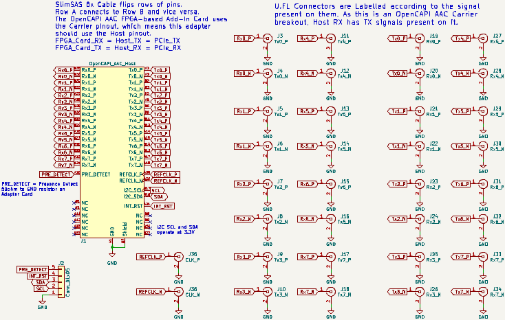
All differential pairs are length-matched to within 1mm both inter-pair and intra-pair.
The board requires a U10A474200T/U10A474240T SlimSAS 74-Pin Receptacle, up to 34 U.FL/UMCC Surface Mount Receptacles, and a 5-Pin 2.54mm Header or Socket.
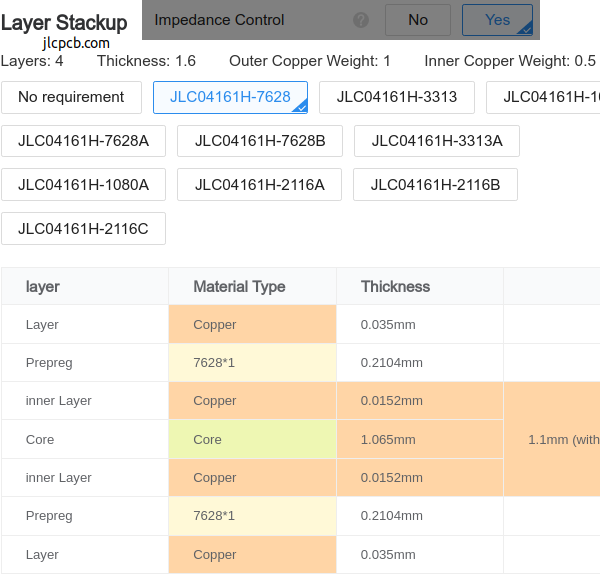
4-Layer PCB stackup taken from JLCPCB.
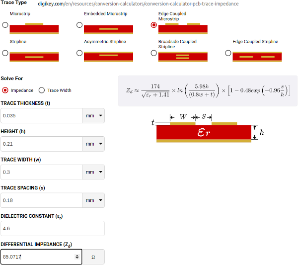
Differential Impedance parameters were calculated using the DigiKey Online Calculator.
| Qty | Value | Footprint | References |
|---|---|---|---|
| 1 | CLK_N | U.FL_w_Label:U.FL_Hirose_w_Label | J36 |
| 1 | CLK_P | U.FL_w_Label:U.FL_Hirose_w_Label | J35 |
| 1 | Conn_01x05 | Connector_PinSocket_2.54mm:PinSocket_1x05_P2.54mm_Vertical | J2 |
| 1 | OpenCAPI_AAC_Host | SlimSAS_8x:SlimSAS_8x_RA_U10-A474 | J1 |
| 1 | Rx0_N | U.FL_w_Label:U.FL_Hirose_w_Label | J20 |
| 1 | Rx0_P | U.FL_w_Label:U.FL_Hirose_w_Label | J19 |
| 1 | Rx1_N | U.FL_w_Label:U.FL_Hirose_w_Label | J22 |
| 1 | Rx1_P | U.FL_w_Label:U.FL_Hirose_w_Label | J21 |
| 1 | Rx2_N | U.FL_w_Label:U.FL_Hirose_w_Label | J24 |
| 1 | Rx2_P | U.FL_w_Label:U.FL_Hirose_w_Label | J23 |
| 1 | Rx3_N | U.FL_w_Label:U.FL_Hirose_w_Label | J26 |
| 1 | Rx3_P | U.FL_w_Label:U.FL_Hirose_w_Label | J25 |
| 1 | Rx4_N | U.FL_w_Label:U.FL_Hirose_w_Label | J28 |
| 1 | Rx4_P | U.FL_w_Label:U.FL_Hirose_w_Label | J27 |
| 1 | Rx5_N | U.FL_w_Label:U.FL_Hirose_w_Label | J30 |
| 1 | Rx5_P | U.FL_w_Label:U.FL_Hirose_w_Label | J29 |
| 1 | Rx6_N | U.FL_w_Label:U.FL_Hirose_w_Label | J32 |
| 1 | Rx6_P | U.FL_w_Label:U.FL_Hirose_w_Label | J31 |
| 1 | Rx7_N | U.FL_w_Label:U.FL_Hirose_w_Label | J34 |
| 1 | Rx7_P | U.FL_w_Label:U.FL_Hirose_w_Label | J33 |
| 1 | Tx0_N | U.FL_w_Label:U.FL_Hirose_w_Label | J4 |
| 1 | Tx0_P | U.FL_w_Label:U.FL_Hirose_w_Label | J3 |
| 1 | Tx1_N | U.FL_w_Label:U.FL_Hirose_w_Label | J6 |
| 1 | Tx1_P | U.FL_w_Label:U.FL_Hirose_w_Label | J5 |
| 1 | Tx2_N | U.FL_w_Label:U.FL_Hirose_w_Label | J8 |
| 1 | Tx2_P | U.FL_w_Label:U.FL_Hirose_w_Label | J7 |
| 1 | Tx3_N | U.FL_w_Label:U.FL_Hirose_w_Label | J10 |
| 1 | Tx3_P | U.FL_w_Label:U.FL_Hirose_w_Label | J9 |
| 1 | Tx4_N | U.FL_w_Label:U.FL_Hirose_w_Label | J12 |
| 1 | Tx4_P | U.FL_w_Label:U.FL_Hirose_w_Label | J11 |
| 1 | Tx5_N | U.FL_w_Label:U.FL_Hirose_w_Label | J14 |
| 1 | Tx5_P | U.FL_w_Label:U.FL_Hirose_w_Label | J13 |
| 1 | Tx6_N | U.FL_w_Label:U.FL_Hirose_w_Label | J16 |
| 1 | Tx6_P | U.FL_w_Label:U.FL_Hirose_w_Label | J15 |
| 1 | Tx7_N | U.FL_w_Label:U.FL_Hirose_w_Label | J18 |
| 1 | Tx7_P | U.FL_w_Label:U.FL_Hirose_w_Label | J17 |
It measures 50 × 71 mm and has 4 copper layers, 1.61 mm thick.
36 parts. The full list of its parts is on this page, with links to each part's symbol and footprint where PCBKit's library has them.
From the mwrnd/OpenCAPI_Breakout repository on GitHub, at the commit this page was made from: the board is OpenCAPI_Breakout.kicad_pcb and its schematic OpenCAPI_Breakout.kicad_sch. PCBKit opens the board in the browser, with nothing to install.
Its repository publishes it under the BSD-2-Clause licence: you may reuse it on that licence's terms (keep the author's notice, and for a copyleft licence share your changes alike).
joeycastillo/Sensor-Watch
A board replacement for the classic Casio F-91W wristwatch


rjwalters/kicad-tools
Standalone Python tools for parsing and manipulating KiCad schematic and PCB files

mbtaylor1982/ReSDMAC
Verilog code to replace the Commodore SDMAC found in the A3000


dmkfasi/nus-cpu
This tends to re-create Nintendo 64 schematics and lay out a board suitable for portable version