2 layers52.2 × 52.2 mm
Base promicro
google/mozc-devices
Circuit diagrams and firmware source code for Gboard DIY keyboards
30 parts3kApache-2.0

 muhaimin44/ESP32-shield
Custom ESP32 distribution board for robotics and RC vehicles. High-density JST breakout for IBT-2 motor drivers and low-latency ELRS control.
Esp shield 8jst is an open-source printed circuit board by muhaimin44, from the muhaimin44/ESP32-shield repository on GitHub. It is a 2-layer board of 82.9 × 92.6 mm with 30 parts on 33 nets, routed with 187 tracks and 21 vias.
Its parts include 17 connectors, 6 capacitors, 3 diodes, 2 resistors and 1 IC. It belongs with the robots and motor control boards and the ESP32 boards of this library.
A custom-designed KiCad shield for the ESP32 DevKit V1 (30-pin) development board. This board serves as a central connectivity hub, breaking out GPIOs into secure JST connectors and providing dedicated interfacing for an ExpressLRS (ELRS) receiver. It is designed for robotics, RC vehicles, and telemetry applications.
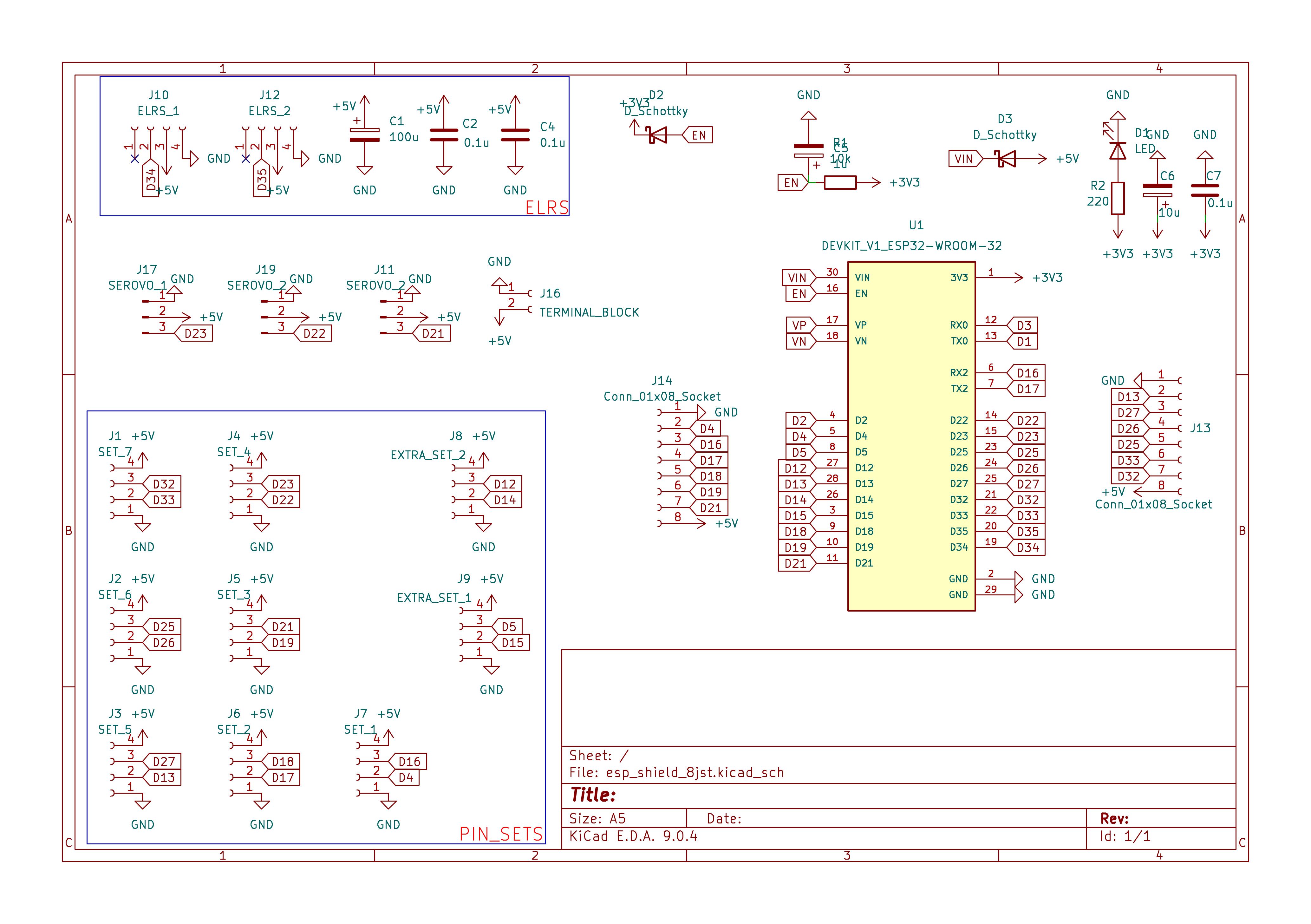
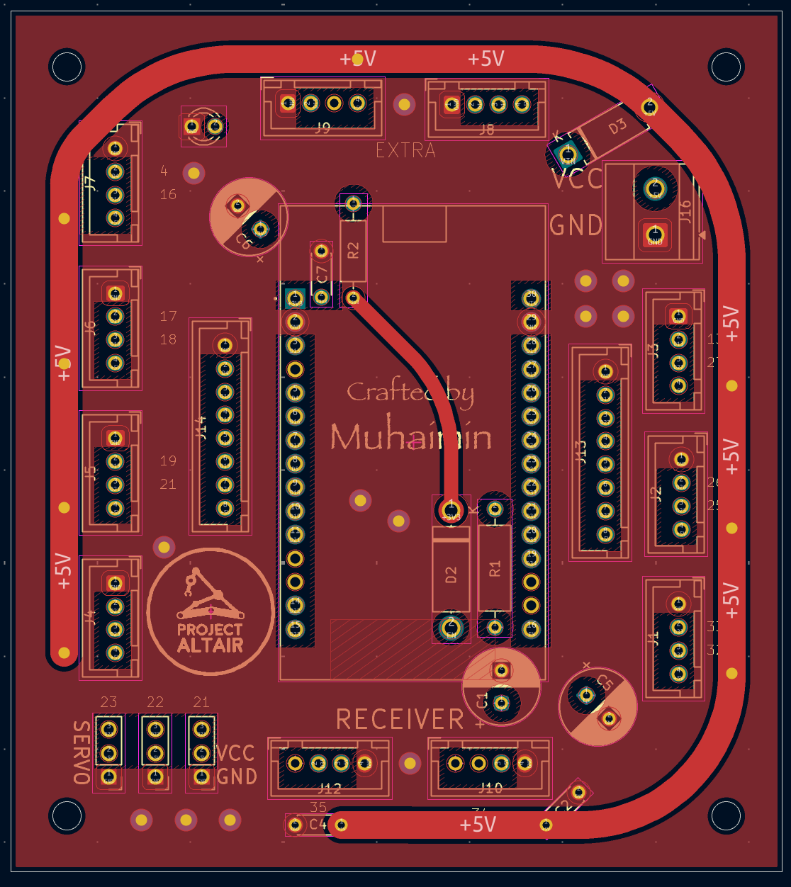
Schematic & Board Layout Visuals
| Schematic Screenshot |
|---|
 |
| Top Layer | Bottom Layer | Silkscreen Layer |
|---|---|---|
 | 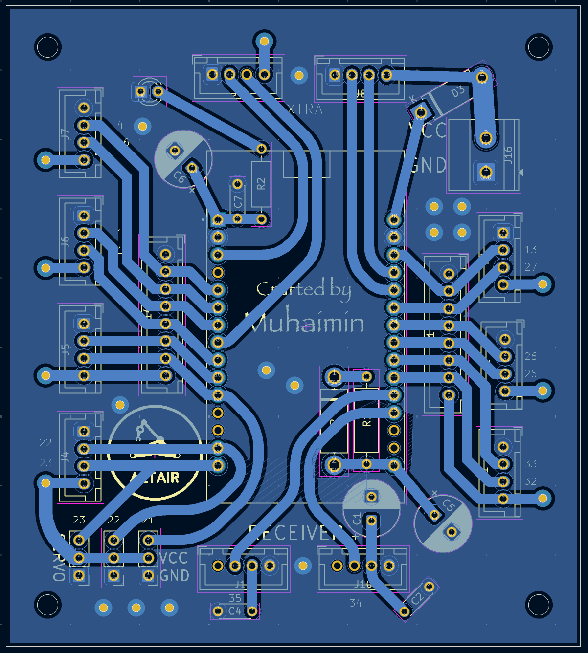 | 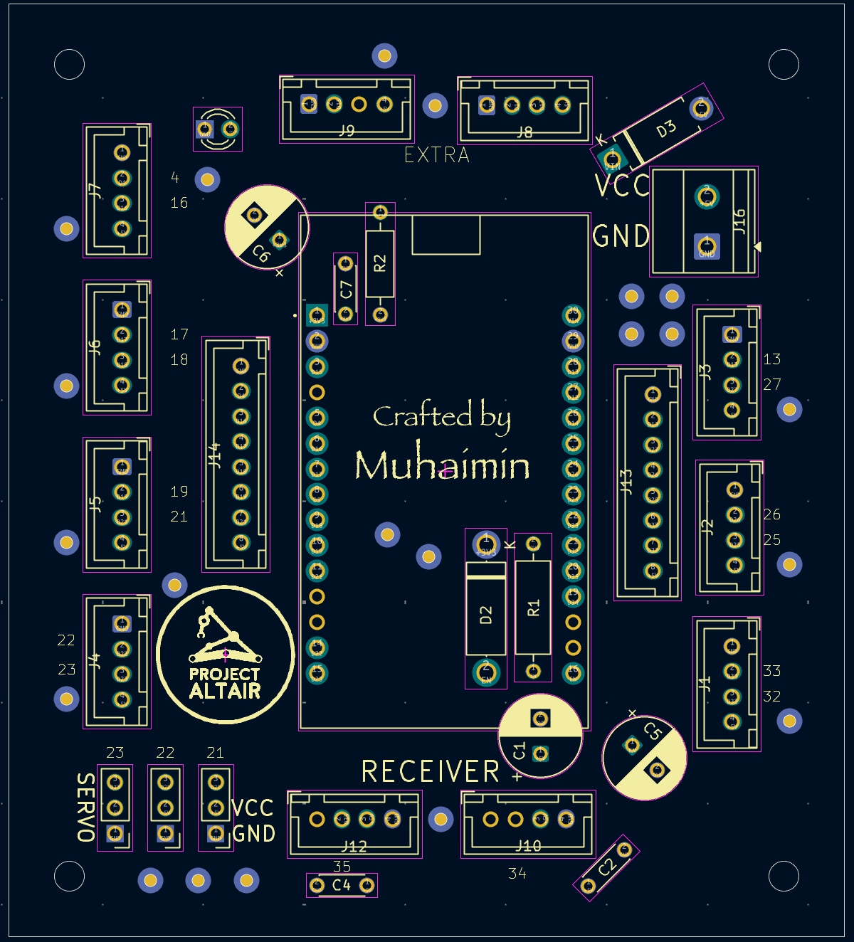 |
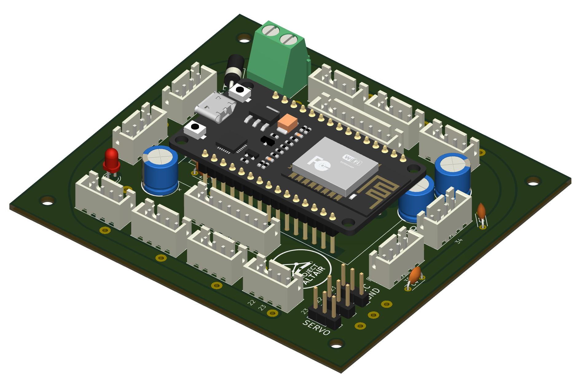 | 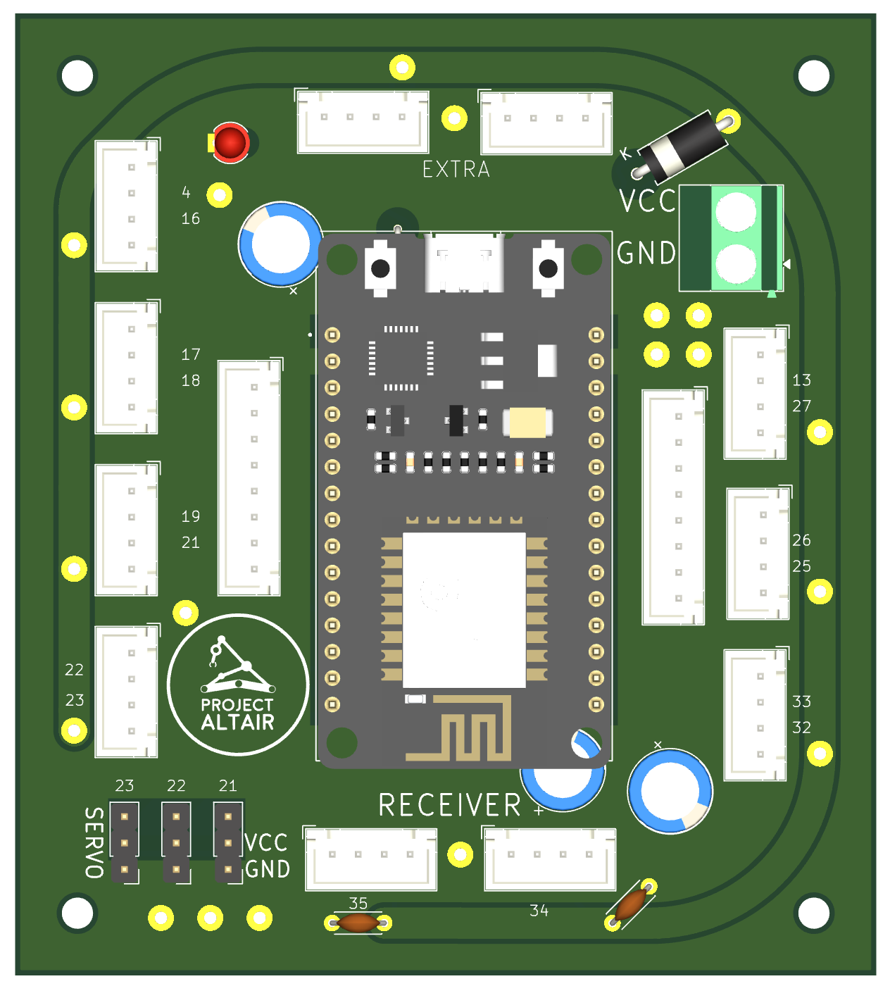 |
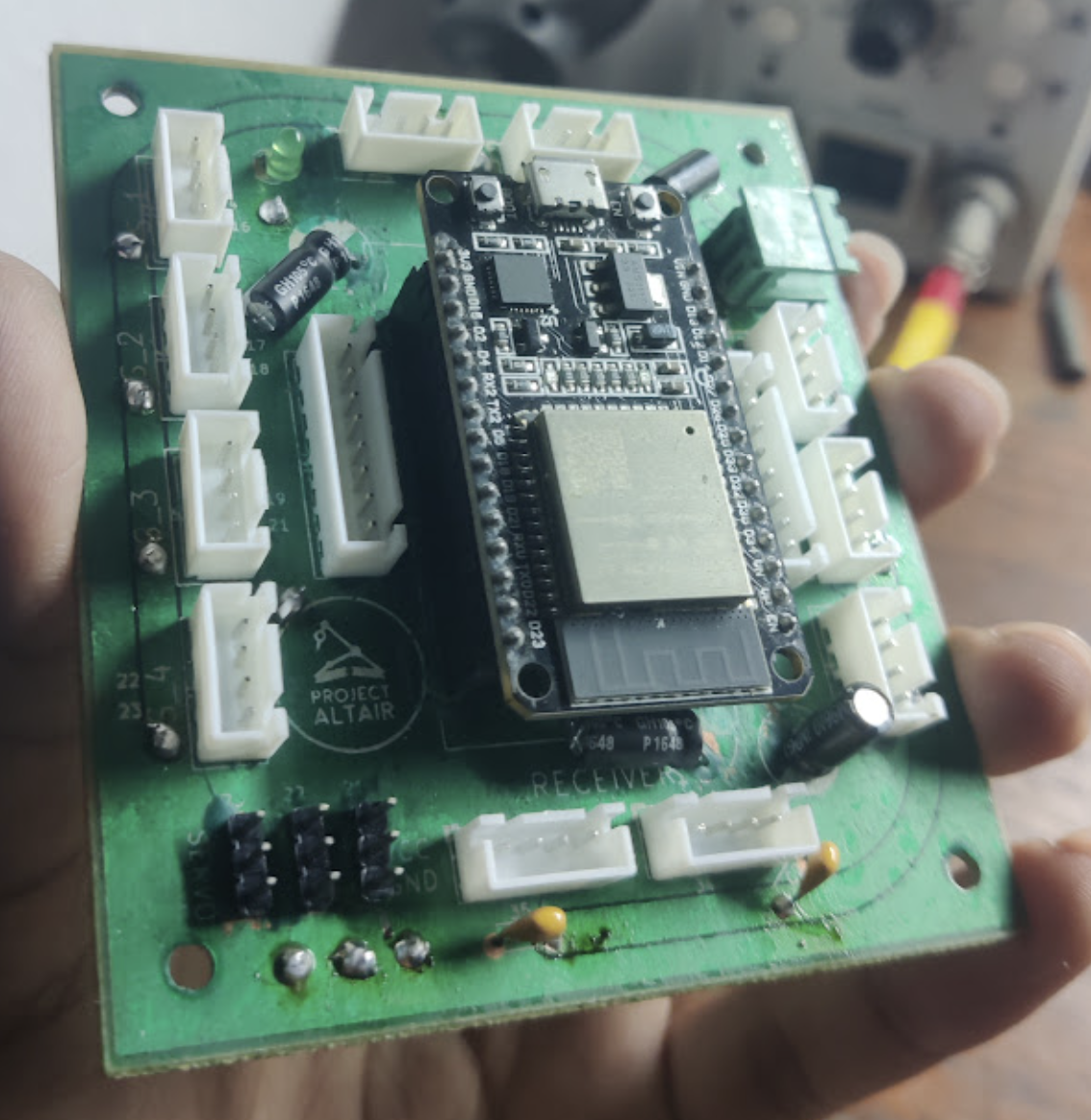 | 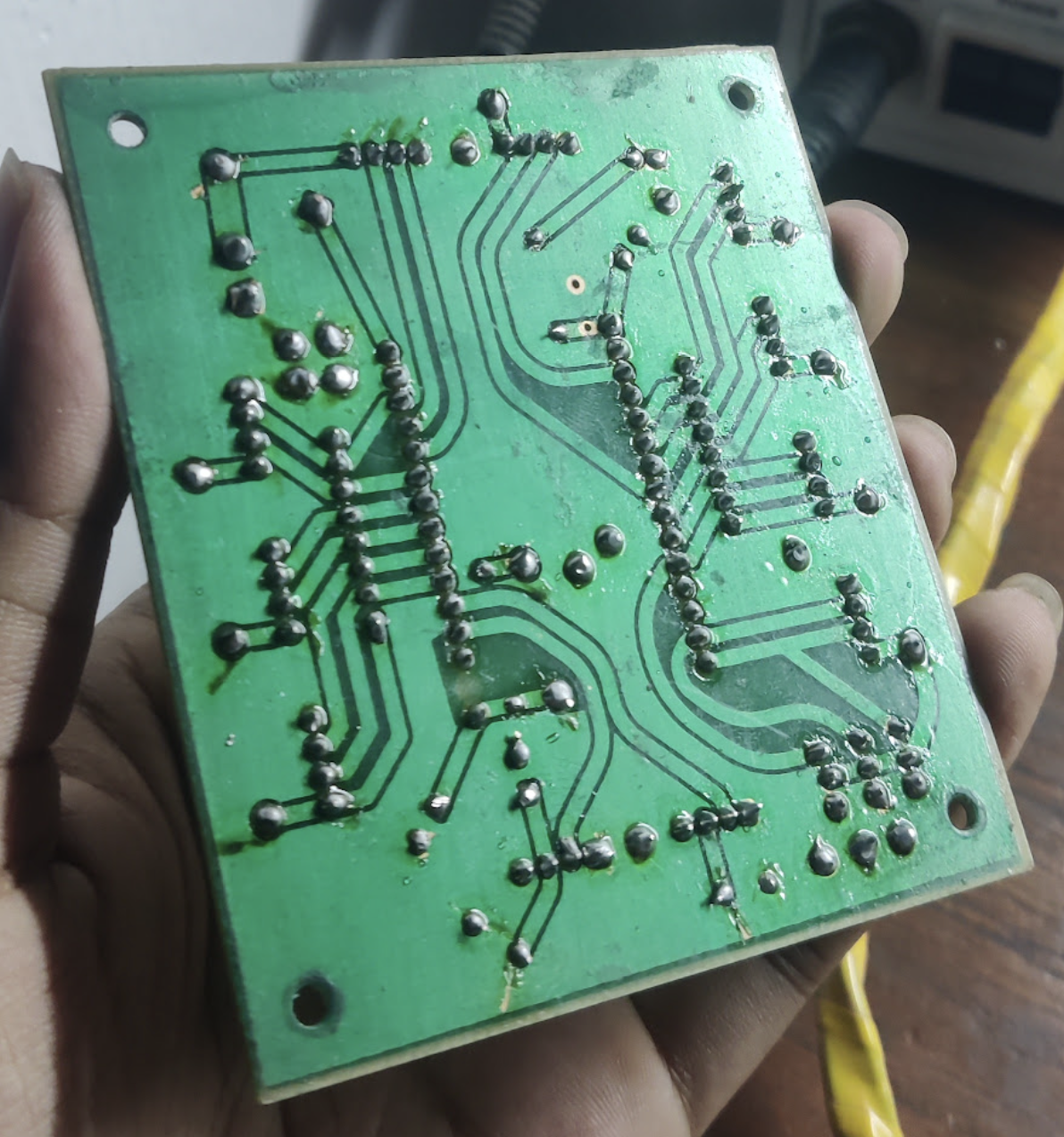 |
J1 to J7) designed to interface with IBT-2 motor drivers. Each port delivers 5V, Ground, and two dedicated hardware PWM signals for independent, bi-directional control of up to 7 motors.J13 and J14) that consolidate power, ground, and 6 PWM signals. These pins are internally bussed directly to 6 of the 7 motor ports, allowing a single 8-pin cable to handle multiple motor drivers and drastically reduce cable clutter.J10 and J12) routed to the ESP32's hardware serial pins for ExpressLRS (ELRS) receivers.D1) is tied directly to the ESP32's 3.3V rail via a current-limiting resistor (R2) to provide visual confirmation of active logic power.C1) on the 3.3V rail absorbs sudden current spikes, preventing accidental brownouts and system resets.C2, C4, C7) are placed on power rails (like the ELRS 5V rail) to block motor-induced voltage ripples from interfering with critical RF control links.D3) is placed between the 5V terminal block input (J16) and the ESP32's VIN pin to act as a one-way safety valve. It blocks power from back-feeding into external supply rails when a USB cable is plugged in for programming, allowing safe flashing of code while the main battery or power supply is connected.Each connector breaks out 5V, GND, and two PWM control signals (PWM A and PWM B) for bi-directional speed control.
| Ref | Type | Pin 1 (GND) | Pin 2 (PWM_B) | Pin 3 (PWM_A) | Pin 4 (+5V) | Target Subsystem / Driver |
|---|---|---|---|---|---|---|
| J1 | 4-Pin JST | GND | GPIO33 | GPIO32 | 5V | Motor 1 Driver Control |
| J2 | 4-Pin JST | GND | GPIO26 | GPIO25 | 5V | Motor 2 Driver Control |
| J3 | 4-Pin JST | GND | GPIO13 | GPIO27 | 5V | Motor 3 Driver Control |
| J4 | 4-Pin JST | GND | GPIO22 | GPIO23 | 5V | Motor 4 Driver Control (Shares pins with Servo 1/3) |
| J5 | 4-Pin JST | GND | GPIO19 | GPIO21 | 5V | Motor 5 Driver Control (Shares pins with Servo 2) |
| J6 | 4-Pin JST | GND | GPIO17 | GPIO18 | 5V | Motor 6 Driver Control |
| J7 | 4-Pin JST | GND | GPIO4 | GPIO16 | 5V | Motor 7 Driver Control |
These connectors bus the power, ground, and PWM signals of multiple motor channels into single headers to simplify wiring.
J13 Consolidates Motors 1, 2, & 3:
| Pin 1 | Pin 2 | Pin 3 | Pin 4 | Pin 5 | Pin 6 | Pin 7 | Pin 8 |
|---|---|---|---|---|---|---|---|
| GND | GPIO13 (M3_B) | GPIO27 (M3_A) | GPIO26 (M2_B) | GPIO25 (M2_A) | GPIO33 (M1_B) | GPIO32 (M1_A) | +5V |
J14 Consolidates Motors 5, 6, & 7:
| Pin 1 | Pin 2 | Pin 3 | Pin 4 | Pin 5 | Pin 6 | Pin 7 | Pin 8 |
|---|---|---|---|---|---|---|---|
| GND | GPIO4 (M7_B) | GPIO16 (M7_A) | GPIO17 (M6_B) | GPIO18 (M6_A) | GPIO19 (M5_B) | GPIO21 (M5_A) | +5V |
Dedicated ports for ELRS receivers. Note the design details and limitations below:
| Ref | Type | Pin 1 | Pin 2 (RX) | Pin 3 | Pin 4 | Notes |
|---|---|---|---|---|---|---|
| J10 (ELRS_1) | 4-Pin JST | NC | GPIO34 | +5V | GND | Primary functional ELRS port |
| J12 (ELRS_2) | 4-Pin JST | NC | GPIO35 | +5V | GND | Secondary functional ELRS port |
Standard 3-pin servo headers (GND, 5V, Signal).
| Ref | Type | Pin 1 (GND) | Pin 2 (+5V) | Pin 3 (Signal) | Notes |
|---|---|---|---|---|---|
| J17 (Servo_1) | 3-Pin Header | GND | 5V | GPIO23 | Shares pin with J4 Pin 3 (Motor 4 PWM_A) |
| J11 (Servo_2) | 3-Pin Header | GND | 5V | GPIO21 | Shares pin with J5 Pin 3 (Motor 5 PWM_A) |
| J19 (Servo_3) | 3-Pin Header | GND | 5V | GPIO22 | Shares pin with J4 Pin 2 (Motor 4 PWM_B) |
Breakout headers for general-purpose expansion.
| Ref | Type | Pin 1 (GND) | Pin 2 | Pin 3 | Pin 4 (+5V) | Notes |
|---|---|---|---|---|---|---|
| J9 (Extra_1) | 4-Pin JST | GND | GPIO15 | GPIO5 | 5V | Skeptic |
| J8 (Extra_2) | 4-Pin JST | GND | GPIO14 | GPIO12 | 5V | Skeptic |
Power terminals and system indicator LEDs.
| Ref | Type | Connections | Purpose |
|---|---|---|---|
| J16 (5V_IN) | Terminal Block | Pin 1: GND, Pin 2: +5V | Main 5V DC power input |
| D1 (LED) | 3mm TH LED | Anode connected to 3.3V via 220Ω | 3.3V logic power status indicator |
Before writing firmware or deploying the board, review these hardware bugs and resource conflicts:
[!IMPORTANT] To avoid hardware damage and signal contention, do not initialize conflicting peripherals in firmware:
- Motor 4 vs. Servos 1 & 3:
J4(Motor 4 control) sharesGPIO23withJ17(Servo 1) andGPIO22withJ19(Servo 3).- Motor 5 vs. Servo 2:
J5(Motor 5 control) sharesGPIO21withJ11(Servo 2).
[!NOTE]
- ESP32
GPIO34andGPIO35are hardware-level input-only pins.- Since ELRS receiver ports (
J10/J12) route to these pins, only receiver-to-ESP32 transmission (RX) is supported. The ESP32 cannot transmit data back to the receiver (TX is unconnected), meaning telemetry telemetry links are not supported on these ports.
Copy and paste this snippet into your project (pins.h) to quickly define the hardware mappings:
/**
 * @file pins.h
 * @brief Hardware pin mapping definitions for ESP32 Shield Rev 1.0.
 * @note Review the README for pin conflict and footprint routing warnings.
 */

#ifndef PINS_H
#define PINS_H

// ==========================================
// 1. Motor Drivers (IBT-2 PWM Signals)
// ==========================================
#define MOTOR1_PWM_A  32
#define MOTOR1_PWM_B  33

#define MOTOR2_PWM_A  25
#define MOTOR2_PWM_B  26

#define MOTOR3_PWM_A  27
#define MOTOR3_PWM_B  13

#define MOTOR4_PWM_A  23  // Shared with Servo 1
#define MOTOR4_PWM_B  22  // Shared with Servo 3
| Reference Designator | Qty | Value / Part | KiCad Footprint | Notes |
|---|---|---|---|---|
| U1 | 1 | ESP32 DevKit V1 (30-pin) | MODULE_DEVKIT_V1_ESP32-WROOM-32 | Main controller |
| J1 to J7 | 7 | Motor Drivers (4-Pin) | JST_XH_B4B-XH-A_1x04_P2.50mm_Vertical | JST-XH 4-Pin |
| J8, J9, J10, J12 | 4 | Extra / ELRS (4-Pin) | JST_XH_B4B-XH-A_1x04_P2.50mm_Vertical | JST-XH 4-Pin |
| J13, J14 | 2 | Consolidated (8-Pin) | JST_XH_B8B-XH-A_1x08_P2.50mm_Vertical | JST-XH 8-Pin |
| J11, J17, J19 | 3 | Servo / 3-Pin Headers | PinHeader_1x03_P2.54mm_Vertical | 2.54mm pitch |
| J16 | 1 | Terminal Block (5V_IN) | TerminalBlock_Phoenix_MKDS-1,5-2_1x02_P5.00mm | 2-pin screw block |
| C1 | 1 | 100µF | Capacitor_THT:CP_Radial_D8.0mm_P3.50mm | Electrolytic (3.3V decoupling) |
| C5 | 1 | 1µF | Capacitor_THT:CP_Radial_D8.0mm_P3.50mm | Electrolytic |
| C6 | 1 | 10µF | Capacitor_THT:CP_Radial_D8.0mm_P3.50mm | Electrolytic |
| C2, C4, C7 | 3 | 0.1µF | Capacitor_THT:C_Disc_D4.3mm_W1.9mm_P5.00mm | Ceramic disc |
| D1 | 1 | 3mm Red LED | LED_THT:LED_D3.0mm | Power status |
| D2, D3 | 2 | Schottky Diode (e.g. 1N5819) | Diode_THT:D_5W_P12.70mm_Horizontal | Safety blocking diodes |
| R1 | 1 | 10kΩ | Resistor_THT:R_Axial_DIN0309_L9.0mm_Horizontal | Reset pull-up |
| R2 | 1 | 220Ω | Resistor_THT:R_Axial_DIN0207_L6.3mm_Horizontal | LED current limiter |
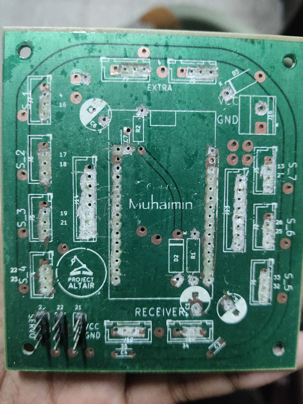
Because of a manufacturing offset error and the lack of plated-through hole connectivity on this revision, perform the following assembly steps carefully:
[!CAUTION] 1. Copper Zone Clearance (Short Circuit Risk)
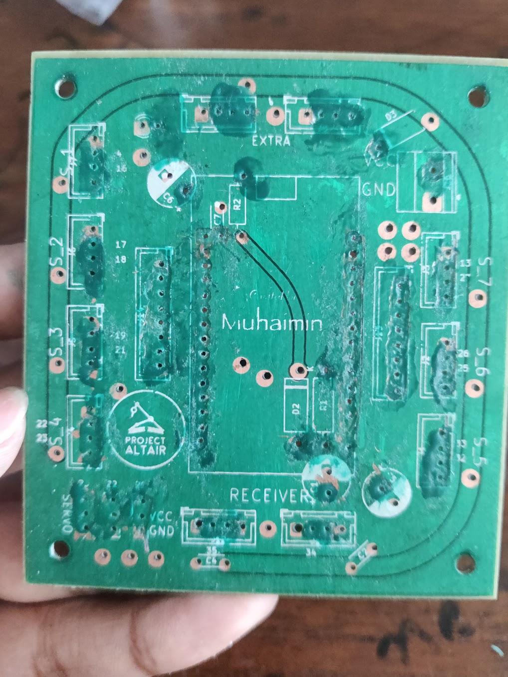
- During manufacturing, the top copper layer shifted slightly to the right. The copper ground fill is dangerously close to several component through-holes.
- Rework Action: Before soldering, inspect the board under magnification. Use an anti-cutter tool to scrape away overlapping copper around component leads that are close to the ground plane, and re-insulate the exposed areas with solder mask.
Reference Images:
Scraped Copper Corrected Solder Mask Reapplied
[!IMPORTANT] 2. Double-Sided Solder Joints (Layer Bridging)
- The PCB does not have plated-through vias for components. It relies on the component leads themselves to bridge signals between the top and bottom copper layers.
- Solder Action: Solder the component pins on both the top and bottom sides of the PCB for:
- C2, C4 (Decoupling Caps)
- R2 (3.3V terminal)
- D2 (Diode pins)
⚠️ CRITICAL: If you only solder the bottom side, the top copper traces will remain disconnected, breaking logic loops.
[!IMPORTANT] 3. Power & Ground Via Stitching
- All dedicated 5V and GND via holes must be manually bridged.
- Stitching Action: Feed a small piece of component lead wire or bus wire through each power and ground via hole, and solder it securely on both the top and bottom copper layers to form complete power loops.
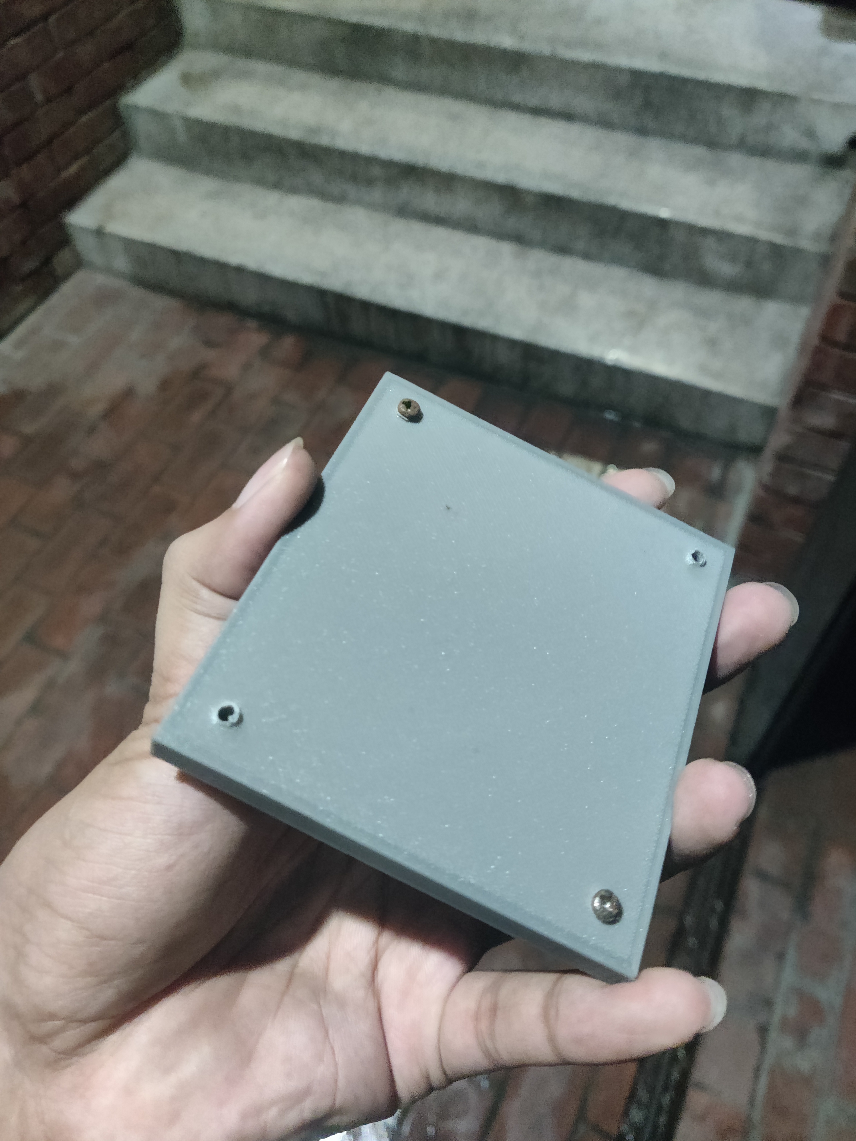
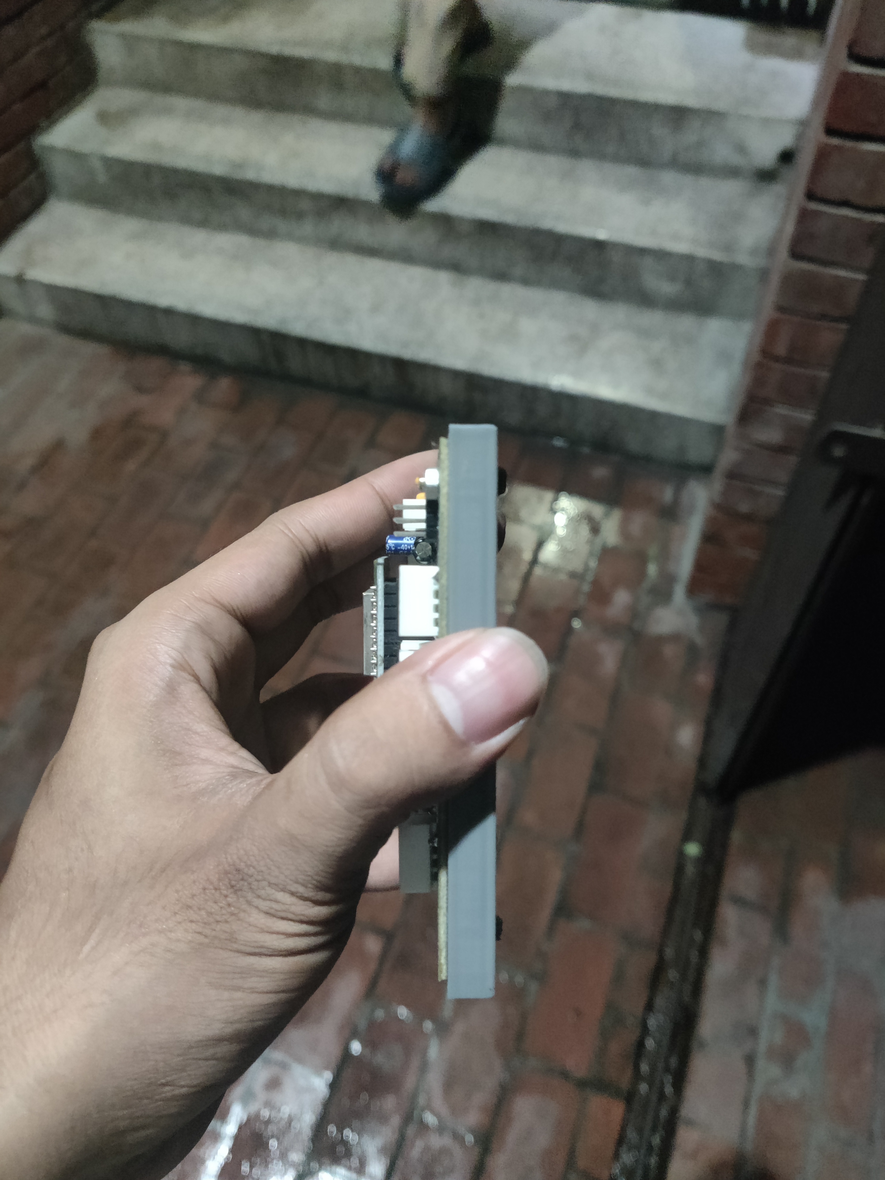
A 3D-printable Bottom Enclosure (or Base Guard) is included in this repository to isolate the exposed underside of the PCB. It bolts directly to the bottom of the board with M3 screws, protecting the manual via stitches and through-hole pins from getting scraped, damaged, or accidentally shorted against conductive surfaces during operation.
📦 Download the 3D Model: Shield_Base_Guard.stl
| 3D CAD Render |
|---|
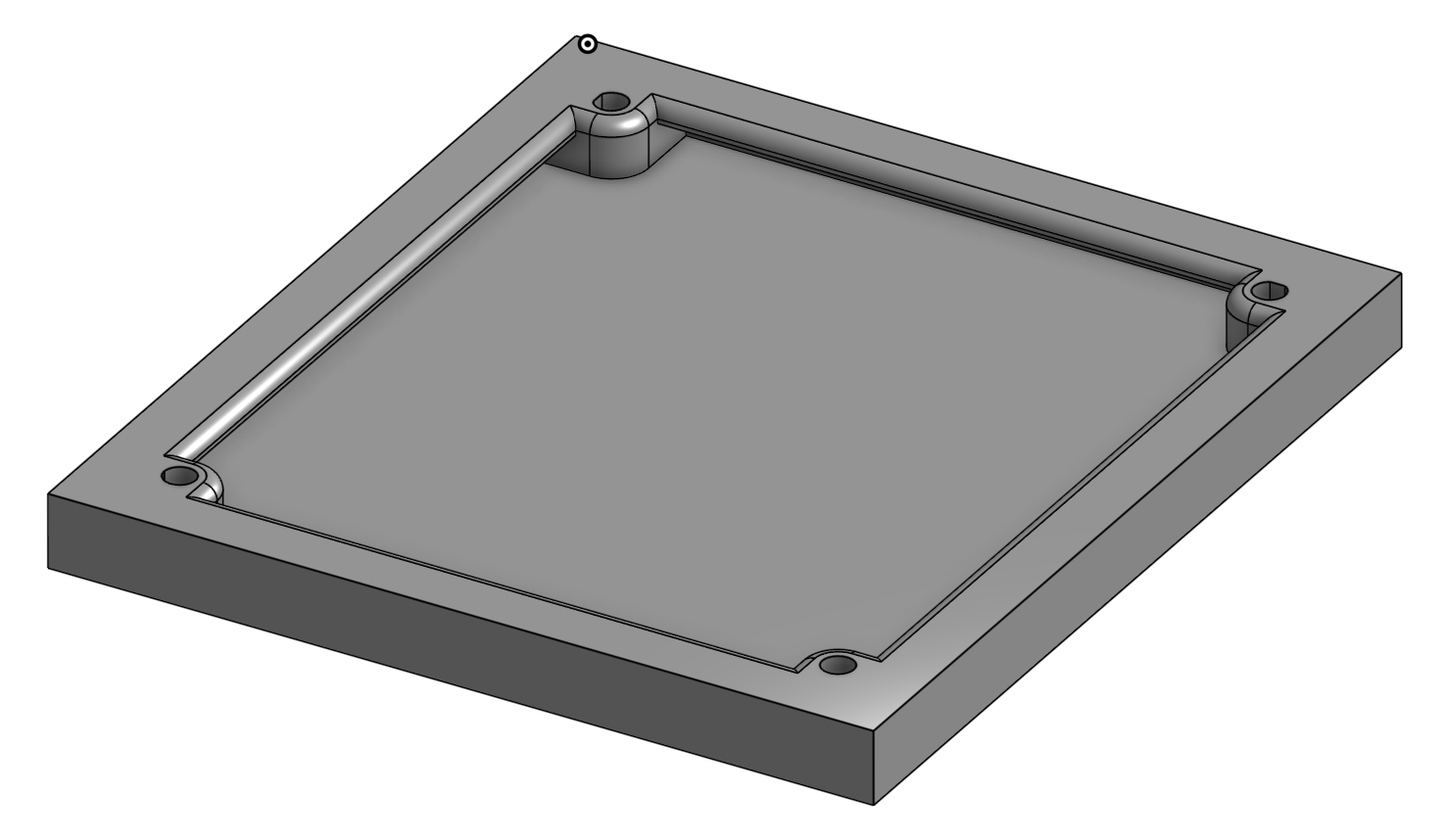 |
| Physical Assembly (Top View) | Physical Assembly (Bottom View) | Physical Assembly (Side View) |
|---|---|---|
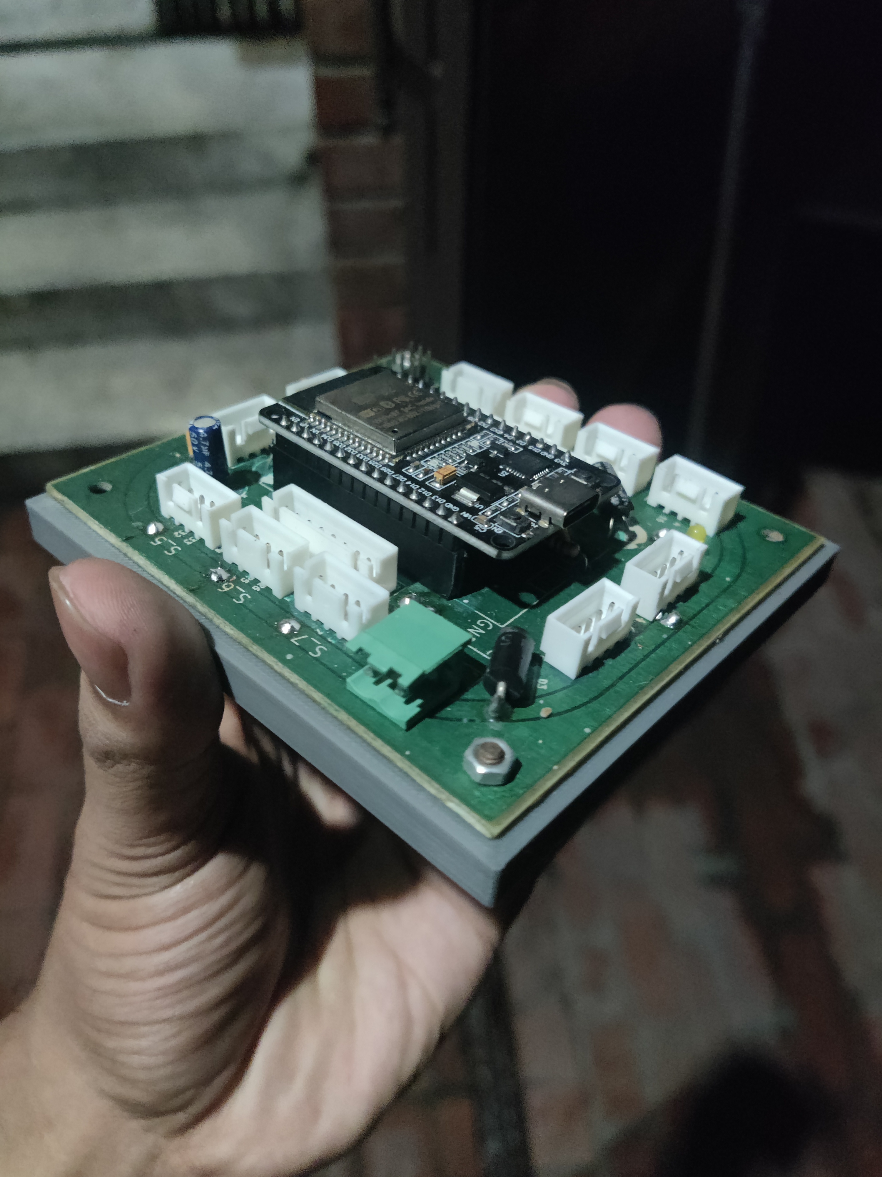 |  |  |
If you want to manufacture this board yourself, all necessary production assets are pre-exported and located in the manufacturing_files/ directory:
| Qty | Value | Footprint | References |
|---|---|---|---|
| 3 | 0.1u | Capacitor_THT:C_Disc_D4.3mm_W1.9mm_P5.00mm | C2, C4, C7 |
| 2 | Conn_01x08_Socket | Connector_JST:JST_XH_B8B-XH-A_1x08_P2.50mm_Vertical | J13, J14 |
| 2 | SEROVO_2 | Connector_PinHeader_2.54mm:PinHeader_1x03_P2.54mm_Vertical | J11, J19 |
| 1 | 100u | Capacitor_THT:CP_Radial_D8.0mm_P3.50mm | C1 |
| 1 | 10k | Resistor_THT:R_Axial_DIN0309_L9.0mm_D3.2mm_P12.70mm_Horizontal | R1 |
| 1 | 10u | Capacitor_THT:CP_Radial_D8.0mm_P3.50mm | C6 |
| 1 | 1u | Capacitor_THT:CP_Radial_D8.0mm_P3.50mm | C5 |
| 1 | 220 | Resistor_THT:R_Axial_DIN0207_L6.3mm_D2.5mm_P10.16mm_Horizontal | R2 |
| 1 | DEVKIT_V1_ESP32-WROOM-32 | DEVKIT_V1_ESP32-WROOM-32:MODULE_DEVKIT_V1_ESP32-WROOM-32 | U1 |
| 1 | D_Schottky | Diode_THT:D_5W_P12.70mm_Horizontal | D2 |
| 1 | D_Schottky | Diode_THT:D_DO-15_P10.16mm_Horizontal | D3 |
| 1 | ELRS_1 | Connector_JST:JST_XH_B4B-XH-A_1x04_P2.50mm_Vertical | J10 |
| 1 | ELRS_2 | Connector_JST:JST_XH_B4B-XH-A_1x04_P2.50mm_Vertical | J12 |
| 1 | EXTRA_SET_1 | Connector_JST:JST_XH_B4B-XH-A_1x04_P2.50mm_Vertical | J9 |
| 1 | EXTRA_SET_2 | Connector_JST:JST_XH_B4B-XH-A_1x04_P2.50mm_Vertical | J8 |
| 1 | LED | LED_THT:LED_D3.0mm | D1 |
| 1 | LOGO | logos:altair_logo | G*** |
| 1 | SEROVO_1 | Connector_PinHeader_2.54mm:PinHeader_1x03_P2.54mm_Vertical | J17 |
| 1 | SET_1 | Connector_JST:JST_XH_B4B-XH-A_1x04_P2.50mm_Vertical | J7 |
| 1 | SET_2 | Connector_JST:JST_XH_B4B-XH-A_1x04_P2.50mm_Vertical | J6 |
| 1 | SET_3 | Connector_JST:JST_XH_B4B-XH-A_1x04_P2.50mm_Vertical | J5 |
| 1 | SET_4 | Connector_JST:JST_XH_B4B-XH-A_1x04_P2.50mm_Vertical | J4 |
| 1 | SET_5 | Connector_JST:JST_XH_B4B-XH-A_1x04_P2.50mm_Vertical | J3 |
| 1 | SET_6 | Connector_JST:JST_XH_B4B-XH-A_1x04_P2.50mm_Vertical | J2 |
| 1 | SET_7 | Connector_JST:JST_XH_B4B-XH-A_1x04_P2.50mm_Vertical | J1 |
| 1 | TERMINAL_BLOCK | TerminalBlock_Phoenix:TerminalBlock_Phoenix_MKDS-1,5-2_1x02_P5.00mm_Horizontal | J16 |
It measures 82.9 × 92.6 mm and has 2 copper layers, 1.6 mm thick.
30 parts. The full list of its parts is on this page, with links to each part's symbol and footprint where PCBKit's library has them.
From the muhaimin44/ESP32-shield repository on GitHub, at the commit this page was made from: the board is esp_shield_8jst/esp_shield_8jst.kicad_pcb and its schematic esp_shield_8jst/esp_shield_8jst.kicad_sch. PCBKit opens the board in the browser, with nothing to install.
Its repository states no licence, so its author keeps all rights: ask muhaimin44 before reusing the design.
google/mozc-devices
Circuit diagrams and firmware source code for Gboard DIY keyboards


VoronDesign/Voron-Hardware
Cool Hardware designed by the Voron Design group

hoglet67/RGBtoHDMI
Bare-metal Raspberry Pi project that provides pixel-perfect sampling of Retro Computer RGB/YUV video and conversion to HDMI

tenderlove/initial-v
It's a BMW shifter converted to a Bluetooth Keyboard that you use with Vim

hackclub/OnBoard
💡 Join 1,000 teenagers and make your first PCB with a $100 grant!

