4 layers158.8 × 104.1 mm

 MST6170/ADD2go2
Wireless Fernanzeige für die Dinamica-Generale-ADD2-Waage am Siloking-Mischwagen — überträgt Gewichtsdaten kabellos zum Radlader-Display oder Smartphone. ESP32-basiert, mit optionaler Schaufel-Wiegung über Drucksensor.
Add2go pcb is an open-source printed circuit board by MST6170, from the MST6170/ADD2go repository on GitHub. It is a 2-layer board of 59 × 68 mm with 31 parts on 58 nets, routed with 280 tracks and 18 vias.
It is built around the K7805M-1000R3, K7812M-1000R3 and MAX3232ID, with the 1.5KE18A among its other parts. Its parts include 11 capacitors, 7 connectors, 3 resistors, 3 ICs and 2 diodes. It belongs with the lEDs and displays boards and the ESP32 boards of this library.


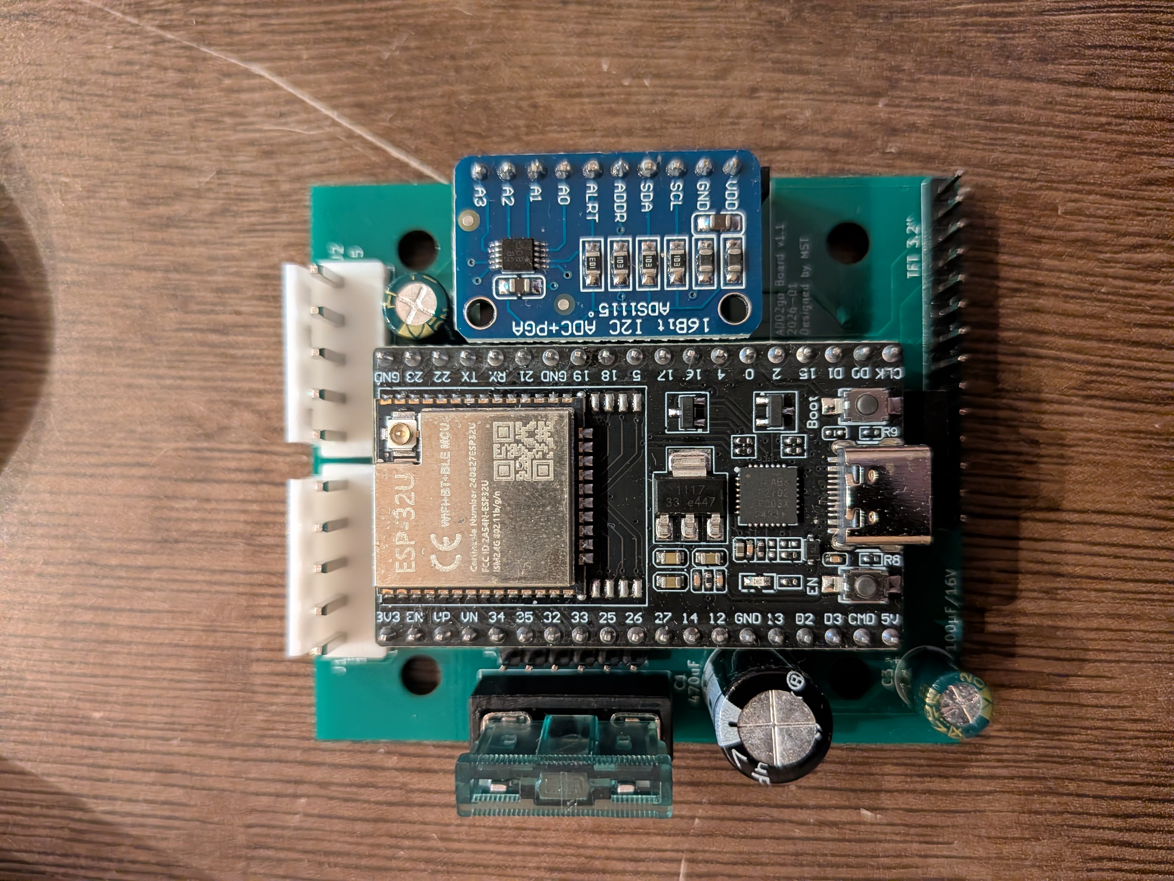 Fertiges Empfänger-Modul auf Basis dieser Platine
Universelle Platine für ADD2go — kann je nach Bestückung entweder als Sender (im Mischwagen, Anschluss an die ADD2-Waage über RS232) oder als Empfänger (im Radlader, mit TFT-Display und Drucksensor für die Schaufel-Wiegung) verwendet werden. Beide Varianten teilen das gleiche Board.
Version 1 — bestellt bei JLCPCB, getestet, läuft produktiv.
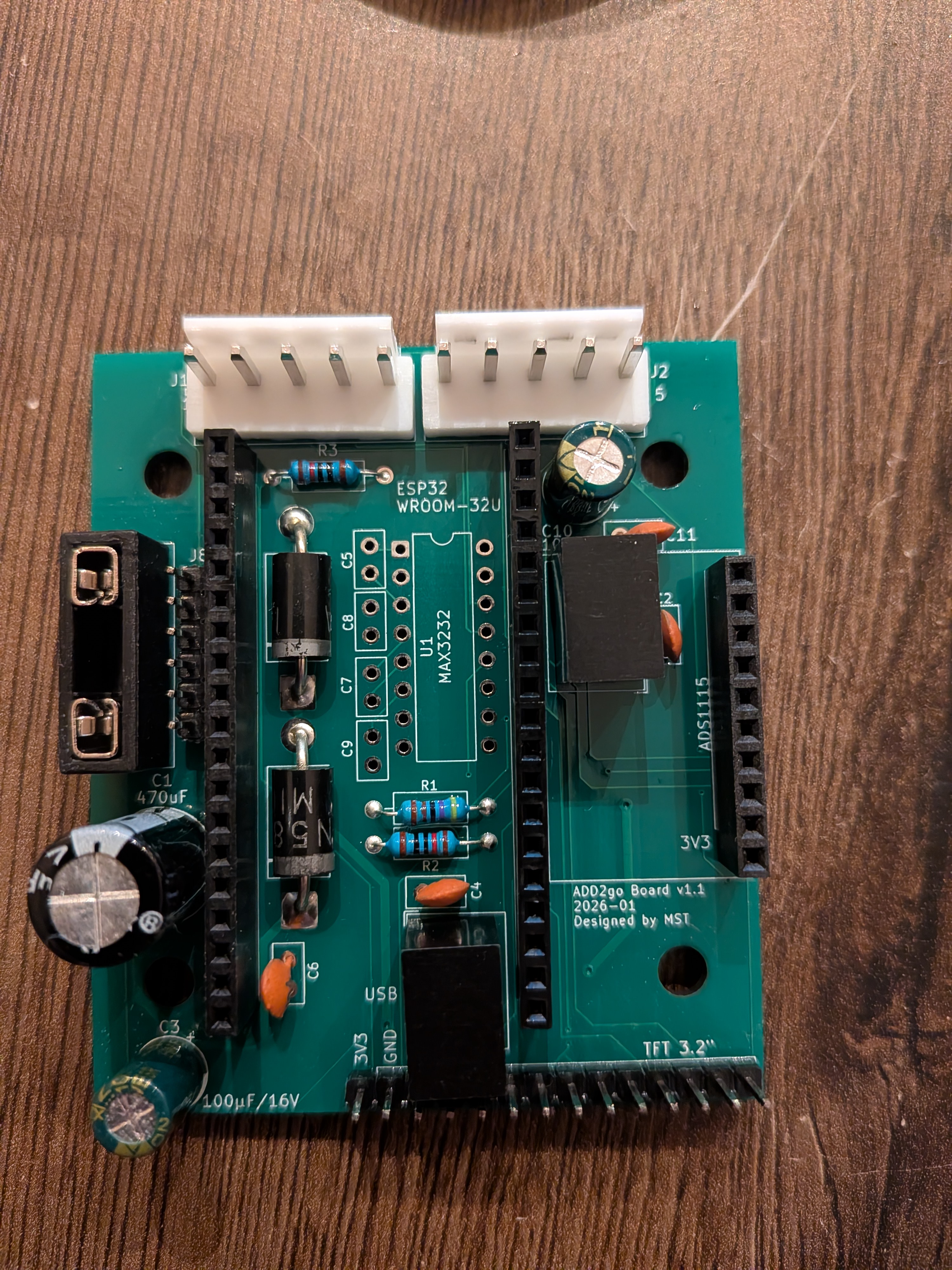 Bestückte Platine in Empfänger-Konfiguration
| Bauteil | Typ | Funktion | Bestückt bei |
|---|---|---|---|
| ESP32-Sockel | Pin-Header 10 + 19 | Modulträger ESP32-WROOM-32U | Sender + Empfänger |
| MAX3232 | Interface-IC | RS232-Pegelwandler | nur Sender |
| K7805M-1000R3 | Mornsun Schaltregler | 12 V → 5 V (~95 % Wirkungsgrad) | Sender + Empfänger |
| K7812M-1000R3 | Mornsun Schaltregler | 12 V stabilisiert (für Drucksensor) | nur Empfänger |
| 1N5822 | Schottky-Diode | Verpolschutz Eingang | Sender + Empfänger |
| 1.5KE18A | TVS-Diode 18 V | Überspannungsschutz | Sender + Empfänger |
| Sicherung | Fuse | Eingangsschutz | Sender + Empfänger |
| Elkos | 100 µF / 16 V, 470 µF | Pufferkondensatoren Versorgung | Sender + Empfänger |
| Kerkos | 100 nF (mehrfach) | MAX3232-Ladekondensatoren + Stützkapazitäten | applikationsabhängig |
| 4k7, 10k | Widerstand | Pull-up / Pull-down | applikationsabhängig |
| Header | Pinzahl | Funktion |
|---|---|---|
| WI-NET (M16) | 5-polig | Anschluss an die ADD2-Waage (Sender) bzw. Versorgung (Empfänger) |
| TFT | 14-polig | ILI9341 3.2" Display + Touch (nur Empfänger-Bestückung) |
| ADS1115 | 6-polig | I²C-Modul für Drucksensor (nur Empfänger-Bestückung) |
| ESP32 | 10 + 19 | Sockel für das ESP32-WROOM-32U-Modul |
📌 Pinbelegung des WI-NET-Steckers und alle ESP32-Pin-Zuordnungen stehen in der Haupt-README.
| Parameter | Wert |
|---|---|
| Lagen | 2 (F.Cu / B.Cu) |
| Boardgröße | 59 × 68 mm |
| Boardstärke | 1.6 mm (Standard) |
| Bestückung | reine THT (Through-Hole), manuell |
| Hersteller | bei JLCPCB bestellt |
| Vorderseite | Rückseite |
|---|---|
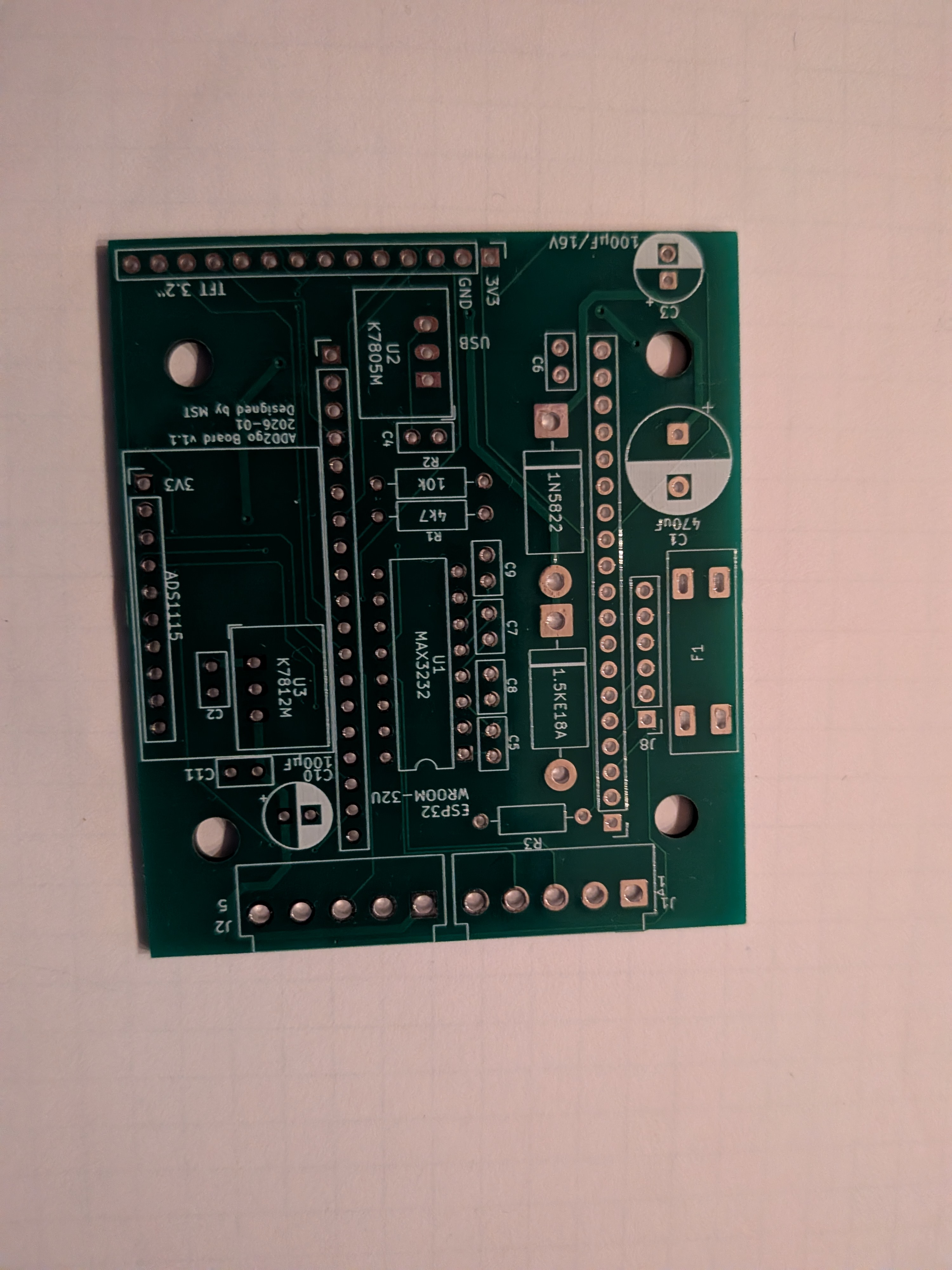 | 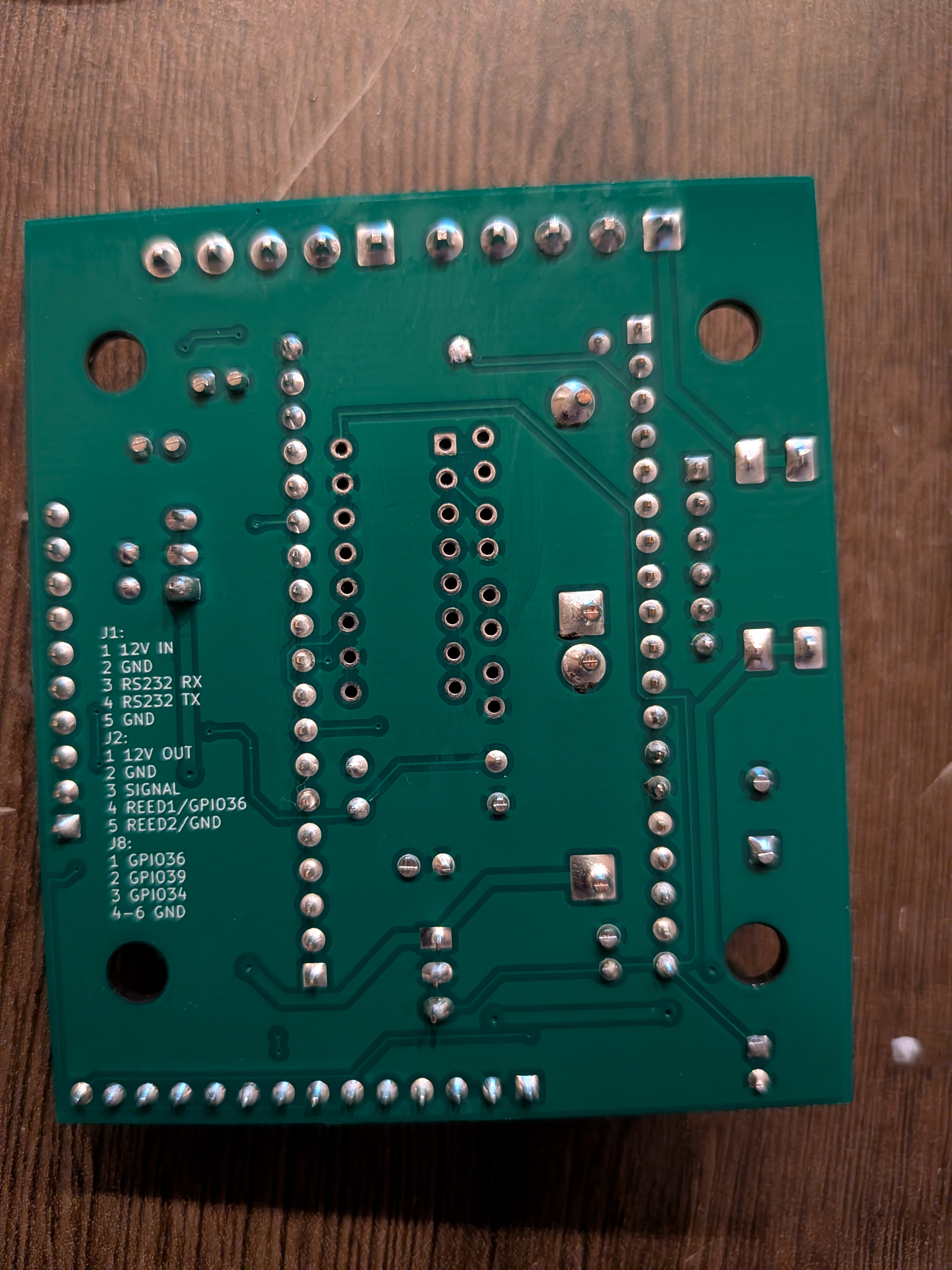 |
Gerber- und Drill-Files sind nicht im Repo enthalten — bei Bedarf in KiCad über File → Plot (Layer F.Cu, B.Cu, F.Mask, B.Mask, F.SilkS, B.SilkS, Edge.Cuts) und File → Fabrication Outputs → Drill Files exportieren.
| Datei | Bedeutung |
|---|---|
add2go_pcb.kicad_pro | KiCad-Projektdatei (Einstellungen, DRC-Regeln) |
add2go_pcb.kicad_sch | Schaltplan (Eeschema) |
add2go_pcb.kicad_pcb | PCB-Layout (Pcbnew) |
Projekt öffnen mit KiCad 9.x über add2go_pcb.kicad_pro.
Hinweis: KiCad legt zusätzlich
*.kicad_prl-Dateien an — die enthalten lokale User-Einstellungen (zuletzt geöffnete Tabs, Fenster-Layout) und sind über.gitignoreausgeschlossen.
Für den Gesamtkontext (ESP32-Pinbelegung, RS232-Protokoll der ADD2-Waage, Pinbelegung des WI-NET-Steckers, vollständige Komponentenliste des Projekts): siehe Haupt-README.
| Qty | Value | Footprint | References |
|---|---|---|---|
| 8 | 100nF | Capacitor_THT:C_Disc_D5.0mm_W2.5mm_P2.50mm | C2, C4, C5, C6, C7, C8, C9, C11 |
| 2 | 10k | Resistor_THT:R_Axial_DIN0207_L6.3mm_D2.5mm_P10.16mm_Horizontal | R2, R3 |
| 2 | Conn_01x05 | Connector_JST:JST_VH_B5P-VH_1x05_P3.96mm_Vertical | J1, J2 |
| 1 | 1.5KE18A | Diode_THT:D_DO-201AD_P15.24mm_Horizontal | D1 |
| 1 | 100µF/16V | Capacitor_THT:CP_Radial_D6.3mm_P2.50mm | C10 |
| 1 | 100µF/25V | Capacitor_THT:CP_Radial_D6.3mm_P2.50mm | C3 |
| 1 | 1N5822 | Diode_THT:D_DO-201AD_P15.24mm_Horizontal | D2 |
| 1 | 470uF/50V | Capacitor_THT:CP_Radial_D10.0mm_P5.00mm | C1 |
| 1 | 4k7 | Resistor_THT:R_Axial_DIN0207_L6.3mm_D2.5mm_P10.16mm_Horizontal | R1 |
| 1 | Conn_01x06 | Connector_PinHeader_2.54mm:PinHeader_1x06_P2.54mm_Vertical | J8 |
| 1 | ESP L | Connector_PinHeader_2.54mm:PinHeader_1x19_P2.54mm_Vertical | J4 |
| 1 | ESP R | Connector_PinHeader_2.54mm:PinHeader_1x19_P2.54mm_Vertical | J5 |
| 1 | Fuse | MST_footprints:FuseHolder_ATO_20mm_THT_2x2 | F1 |
| 1 | Header ADS1115 | Connector_PinHeader_2.54mm:PinHeader_1x10_P2.54mm_Vertical | J3 |
| 1 | K7805M-1000R3 | Converter_DCDC:Converter_DCDC_RECOM_R-78E-0.5_THT | U2 |
| 1 | K7812M-1000R3 | Converter_DCDC:Converter_DCDC_RECOM_R-78E-0.5_THT | U3 |
| 1 | MAX3232 | Package_DIP:DIP-16_W7.62mm | U1 |
| 1 | TFT 3.2" | Connector_PinHeader_2.54mm:PinHeader_1x14_P2.54mm_Vertical | J7 |
The 27 most common of 31 parts.
It measures 59 × 68 mm and has 2 copper layers, 1.6 mm thick.
31 parts, built around the K7805M-1000R3, K7812M-1000R3, MAX3232ID and 1.5KE18A. The full list of its parts is on this page, with links to each part's symbol and footprint where PCBKit's library has them.
From the MST6170/ADD2go repository on GitHub, at the commit this page was made from: the board is add2go_pcb/add2go_pcb.kicad_pcb and its schematic add2go_pcb/add2go_pcb.kicad_sch. PCBKit opens the board in the browser, with nothing to install.
Its repository states no licence, so its author keeps all rights: ask MST6170 before reusing the design.


kunichiko/X68k-MinyasX
MinyasX は、Windows (AT互換機) 用の FDD を無改造で X68000 に接続して使えるようにするアダプタです。

ILikeMice/spymic
Not too many, this is a v1 and i might make a v2 if this thing is good enough! For now, this just takes the 35mm piezos input and amplifies it into a headphone jack, sadly i couldnt add more since the deadline is in a…


Gecesars/ant_control
Acoplador automático de antena HF, aberto e reparável, para estações de até 100 W PEP. O projeto usa uma rede L comutada por relés, medição direcional forward/reflected baseada em ponte tandem-match e controladora…