2 layers100 × 70 mm

 ms02-1337/CRET
Can-bus Reverse Engineering Toolkit
CRET is an open-source printed circuit board by ms02-1337, from the ms02-1337/CRET repository on GitHub, published under the GPL-3.0 licence. It is a 2-layer board with 85 parts on 65 nets, routed with 550 tracks and 74 vias.
It is built around the MCP2551-I/P, GL850G and SY6280AAC. Its parts include 25 capacitors, 18 resistors, 8 ICs, 4 inductors and 3 diodes. It belongs with the interfaces and adapters boards and the PIC boards of this library.


CRET - Can Bus Reverse Engineering Toolkit
Author: Adrian Marcos Batlle


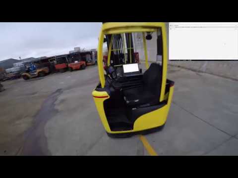
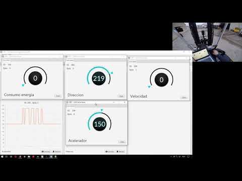
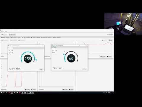
Here are some pictures of the produced hardware:


Copyright (c) 2018 - 2019 Adrian Marcos
This program is free software: you can redistribute it and/or modify it under the terms of the GNU General Public License as published by the Free Software Foundation, either version 3 of the License, or any later version.
| Qty | Value | Footprint | References |
|---|---|---|---|
| 13 | 100nF | Capacitor_SMD:C_1206_3216Metric_Pad1.42x1.75mm_HandSolder | C1, C2, C3, C4, C5, C6, C12, C16, C20, C21, C23, C24, C25 |
| 8 | 1k | Resistor_SMD:R_1206_3216Metric_Pad1.42x1.75mm_HandSolder | R2, R3, R5, R13, R14, R16, R17, R18 |
| 6 | Conn_01x01_Male | TestPoint:TestPoint_Pad_D2.5mm | GND, GND, H-1, H-2, L-1, L-2 |
| 4 | 22pF | Capacitor_SMD:C_1206_3216Metric_Pad1.42x1.75mm_HandSolder | C10, C11, C18, C19 |
| 4 | JUMPER | TestPoint:TestPoint_2Pads_Pitch2.54mm_Drill0.8mm | JP1, JP2, JP3, JP4 |
| 3 | 10k | Resistor_SMD:R_1206_3216Metric_Pad1.42x1.75mm_HandSolder | R7, R10, R11 |
| 3 | 10uF | Capacitor_SMD:C_1206_3216Metric_Pad1.42x1.75mm_HandSolder | C7, C15, C22 |
| 3 | 600R/2A | Resistor_SMD:R_1206_3216Metric_Pad1.42x1.75mm_HandSolder | L2, L3, L4 |
| 3 | TestPoint_Loop_D3.80mm_Drill2.8mm | TestPoint:TestPoint_Loop_D3.80mm_Drill2.8mm | Support1, Support2, Support3 |
| 2 | 0,1uF | Capacitor_SMD:C_1206_3216Metric_Pad1.42x1.75mm_HandSolder | C8, C9 |
| 2 | 100uF | Capacitor_SMD:C_1206_3216Metric_Pad1.42x1.75mm_HandSolder | CP3, CP4 |
| 2 | 120 | Resistor_SMD:R_1206_3216Metric_Pad1.42x1.75mm_HandSolder | R4, R15 |
| 2 | 24Mhz | Crystal:Crystal_SMD_HC49-SD_HandSoldering | Q1, Q2 |
| 2 | 33pF | Capacitor_SMD:C_1206_3216Metric_Pad1.42x1.75mm_HandSolder | C13, C14 |
| 2 | 4,7uF | Capacitor_SMD:C_1206_3216Metric_Pad1.42x1.75mm_HandSolder | CP1, CP2 |
| 2 | 47k | Resistor_SMD:R_1206_3216Metric_Pad1.42x1.75mm_HandSolder | R9, R12 |
| 2 | DB9_Male | Connector_Dsub:DSUB-9_Male_Horizontal_P2.77x2.84mm_EdgePinOffset4.94mm_Housed_MountingHolesOffset7.48mm | CAN1, CAN2 |
| 2 | LOGO | Desktop:forklift | G1, G2 |
| 2 | MCP2515-xSO | Package_SO:SOIC-18W_7.5x11.6mm_P1.27mm | IC2-1, IC2-2 |
| 2 | MCP2551 | Package_SO:SO-8_5.3x6.2mm_P1.27mm | IC3-1, IC3-2 |
| 2 | PIC18F14K50-ESO | Package_SO:SOIC-20W_7.5x12.8mm_P1.27mm | IC1-1, IC1-2 |
| 2 | red | LED_SMD:LED_1206_3216Metric_Pad1.42x1.75mm_HandSolder | LED1, LED2 |
| 1 | 12Mhz | Crystal:Crystal_SMD_HC49-SD_HandSoldering | Q3 |
| 1 | 1uF | Capacitor_SMD:C_1206_3216Metric_Pad1.42x1.75mm_HandSolder | C17 |
| 1 | 4,7k | Resistor_SMD:R_1206_3216Metric_Pad1.42x1.75mm_HandSolder | R1 |
| 1 | 5.1k | Resistor_SMD:R_1206_3216Metric_Pad1.42x1.75mm_HandSolder | R8 |
| 1 | 600R/200mA | Resistor_SMD:R_1206_3216Metric_Pad1.42x1.75mm_HandSolder | L1 |
| 1 | 680 | Resistor_SMD:R_1206_3216Metric_Pad1.42x1.75mm_HandSolder | R6 |
| 1 | CANBUS | Desktop:CANBUS | G3 |
| 1 | D | Diode_SMD:D_1206_3216Metric_Pad1.42x1.75mm_HandSolder | D1 |
| 1 | GL850G | Package_SO:SSOP-28_5.3x10.2mm_P0.65mm | U2 |
| 1 | LOGO | Desktop:pc | G4 |
| 1 | SY6280 | Package_TO_SOT_SMD:SOT-23-5_HandSoldering | U1 |
| 1 | USB_B_Micro | Connector_USB:USB_Micro-B_Molex-105017-0001 | J7 |
85 parts, built around the MCP2551-I/P, GL850G and SY6280AAC. The full list of its parts is on this page, with links to each part's symbol and footprint where PCBKit's library has them.
From the ms02-1337/CRET repository on GitHub, at the commit this page was made from: the board is hardware/scheme/cret.kicad_pcb. PCBKit opens the board in the browser, with nothing to install.
Its repository publishes it under the GPL-3.0 licence: you may reuse it on that licence's terms (keep the author's notice, and for a copyleft licence share your changes alike).


skunkforce/edgy_boards_legacy
small mostly single chip design bits with put_on_edge connectors


spdidle/a-side
A-Side is a cassette tape inspired hub to connect full size SD cards among other things to my laptop. I own several cameras but it's not convenient at all to find my dongle and connect it.

ArthurMLago/botwJoystickGyro
Making any controller have motion controls or use with CEMU