2 layers30 × 61.3 mm
 MrResolution/Code-for-India1
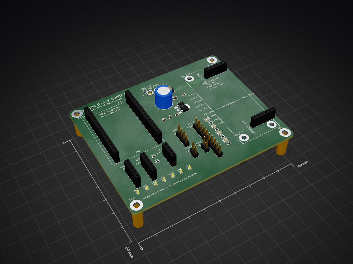
A professional 100mm × 80mm 2-layer FR4 carrier / motherboard PCB designed to interconnect the electronic modules of the 5-DOF robotic arm without hard-soldering microcontrollers or driver ICs.
Robotic arm motherboard is an open-source printed circuit board by MrResolution, from the MrResolution/Code-for-India repository on GitHub. It is a 2-layer board of 100 × 80 mm with 47 parts on 21 nets, routed with 11 tracks and 0 vias.
Its parts include 7 resistors, 6 capacitors, 5 diodes, 1 IC and 1 fuse. It belongs with the computers and single-board computers boards of this library.
Carrier PCB & Backplane · KiCad 7 / 8 · ESP32 DevKit V1 Socket · PCA9685 Module Socket · Dual VL53L1X ToF · XT30 Power
A professional 100mm × 80mm 2-layer FR4 carrier / motherboard PCB designed to interconnect the electronic modules of the 5-DOF robotic arm without hard-soldering microcontrollers or driver ICs. All commercial off-the-shelf (COTS) modules plug directly into standard 2.54mm female pin headers.
| Parameter | Specification |
|---|---|
| Dimensions | 100.0 mm × 80.0 mm |
| Layers | 2-layer FR4, 1.6 mm thickness, 1 oz copper ($35,\mu\text{m}$) |
| Surface Finish | HASL Lead-Free (or ENIG) |
| Mounting Holes | 4× M3 mounting holes at corners with 3.5 mm edge inset (93.0 mm × 73.0 mm spacing) |
| Power Input | XT30 connector (SERVO_V+: 5.0V – 6.0V external DC, 5A–10A capability) |
| Protection | 5A mini blade/SMD fuse (F1) + Schottky reverse polarity diode (D1) + 1000 µF low-ESR bulk electrolytic capacitor (C1) |
| Logic Supply | Onboard AMS1117-3.3 LDO regulator providing clean 3.3V rail from servo power |
| Signal Integrity | Ground planes on bottom layer, wide 2.0 mm power distribution traces, localized 0.1 µF & 10 µF decoupling |
GND, OE (Active-Low Output Enable), SCL, SDA, VCC (3.3V), and V+ (Servo Power).pca9685_mount_bracket.stl and pca9685_mount_bracket.scad) that secures the module cleanly above the PCB.J_VL53_1, J_VL53_2): 3V3, GND, SDA, SCL, XSHUT.3V3, GND, SDA, SCL) with 4.7 kΩ pull-ups.3V3, GND, TX, RX).J_ESTOP) and hardware Servo Enable 2-pin header (J_SRV_EN).robotic_arm_motherboard.kicad_pcb: PCB layout (tracks, pours, footprints, silkscreen).robotic_arm_motherboard.kicad_sch: Schematic with power, sockets, protection, and decoupling.robotic_arm_motherboard.kicad_pro: KiCad 7/8 project configuration.robotic_arm_motherboard_gerbers.zip: Ready-to-upload ZIP for JLCPCB, PCBWay, or OSH Park.production_gerbers/: Individual RS-274X Gerber layers and Excellon NC drill files.BOM.csv: Complete bill of materials with references, values, and footprints.robotic_arm_motherboard-pos.csv: Component pick-and-place centroid positions.robotic_arm_motherboard-pcb.pdf: High-resolution vector schematic and layer plots.robotic_arm_motherboard-3d.step: Full 3D CAD model of the carrier board.pca9685_mount_bracket.stl: 3D printable bracket for the PCA9685 module.pca9685_mount_bracket.scad: Parametric OpenSCAD source file.pcb_layout_diagram.svg: Dimensioned topology and socket arrangement diagram.pcb_render.svg: Top layer vector render.| Qty | Value | Footprint | References |
|---|---|---|---|
| 7 | R_0603_1608Metric | R_0603_1608Metric | R1, R2, R3, R4, R5, R6, R7 |
| 7 | TestPoint_Pad_D1.5mm | TestPoint_Pad_D1.5mm | TP1, TP2, TP3, TP4, TP5, TP6, TP7 |
| 4 | C_0603_1608Metric | C_0603_1608Metric | C3, C4, C5, C6 |
| 4 | LED_0805_2012Metric | LED_0805_2012Metric | LED1, LED2, LED3, LED4 |
| 4 | MountingHole_2.7mm_M2.5_Pad | MountingHole_2.7mm_M2.5_Pad | MH_PCA1, MH_PCA2, MH_PCA3, MH_PCA4 |
| 4 | MountingHole_3.2mm_M3_Pad | MountingHole_3.2mm_M3_Pad | MH1, MH2, MH3, MH4 |
| 2 | PinHeader_1x02_P2.54mm_Vertical | PinHeader_1x02_P2.54mm_Vertical | J_ESTOP, J_SRV_EN |
| 2 | PinSocket_1x05_P2.54mm_Vertical | PinSocket_1x05_P2.54mm_Vertical | J_VL53_1, J_VL53_2 |
| 2 | PinSocket_1x06_P2.54mm_Vertical | PinSocket_1x06_P2.54mm_Vertical | J_PCA9685_AUX, J_PCA9685_CTRL |
| 2 | PinSocket_1x15_P2.54mm_Vertical | PinSocket_1x15_P2.54mm_Vertical | J_ESP32_LEFT, J_ESP32_RIGHT |
| 1 | AMASS_XT30U-F_1x02_P5.0mm_Vertical | AMASS_XT30U-F_1x02_P5.0mm_Vertical | J_SERVO_PWR |
| 1 | CP_Radial_D10.0mm_P5.00mm | CP_Radial_D10.0mm_P5.00mm | C1 |
| 1 | C_0805_2012Metric | C_0805_2012Metric | C2 |
| 1 | D_SMA | D_SMA | D1 |
| 1 | Fuse_1206_3216Metric | Fuse_1206_3216Metric | F1 |
| 1 | PinHeader_1x04_P2.54mm_Vertical | PinHeader_1x04_P2.54mm_Vertical | J_UART |
| 1 | PinHeader_1x10_P2.54mm_Vertical | PinHeader_1x10_P2.54mm_Vertical | J_GPIO_EXP |
| 1 | PinSocket_1x04_P2.54mm_Vertical | PinSocket_1x04_P2.54mm_Vertical | J_I2C_EXP |
| 1 | SOT-223-3_TabPin2 | SOT-223-3_TabPin2 | U1 |
It measures 100 × 80 mm and has 2 copper layers, 1.6 mm thick.
47 parts. The full list of its parts is on this page, with links to each part's symbol and footprint where PCBKit's library has them.
From the MrResolution/Code-for-India repository on GitHub, at the commit this page was made from: the board is hardware/robotic_arm_motherboard/robotic_arm_motherboard.kicad_pcb and its schematic hardware/robotic_arm_motherboard/robotic_arm_motherboard.kicad_sch. PCBKit opens the board in the browser, with nothing to install.
Its repository states no licence, so its author keeps all rights: ask MrResolution before reusing the design.


VoronDesign/Voron-Hardware
Cool Hardware designed by the Voron Design group

hackclub/OnBoard
💡 Join 1,000 teenagers and make your first PCB with a $100 grant!


FrameworkComputer/InputModules
Reference designs and documentation for the Input Module system in the Framework Laptop 16