6 layers100 × 70 mm

 MrNash23/DIGIWAVE
Ham Radio Digi Modes on the T-LoRa Pager
Ft8-pager interface is an open-source printed circuit board by MrNash23, from the MrNash23/DIGIWAVE repository on GitHub, published under the GPL-3.0 licence. It is a 2-layer board of 40 × 25 mm with 50 parts on 31 nets, routed with 463 tracks and 42 vias.
It is built around the ES8311, SN74LVC1G3157DCKR and SMF5.0CA, with the MMBT3904 and SMF15CA among its other parts. Its parts include 13 capacitors, 7 resistors, 3 diodes, 2 ICs and 2 connectors. It belongs with the radio and wireless and interfaces and adapters boards of this library.



Firmware for the LilyGo T-LoRa Pager: FT8, FT4, CW, RTTY, NAVTEX, WEFAX and SSTV on a device that fits in a jacket pocket, and a scanner that tells them apart.
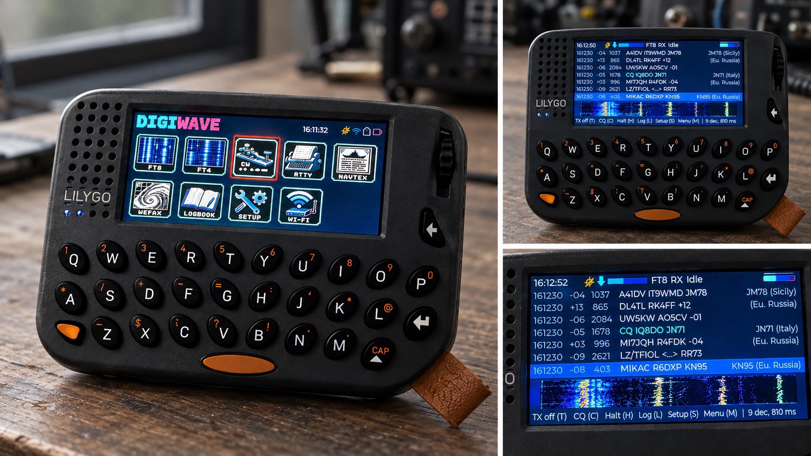
DIGIWAVE listens to the audio of a radio, decodes what it hears and shows it on the pager's display. In the modes that can transmit it also generates the audio and keys the radio. No computer is involved.
 FT8 |  FT4 |  CW |  RTTY |  NAVTEX |  WEFAX |  SSTV |  SCAN |
| Mode | Receive | Transmit |
|---|---|---|
| FT8, FT4 | yes, with locator and country of each station | yes, with automatic QSO sequence and ADIF log |
| CW | yes, in a 100 Hz window that is moved with the wheel | yes, from the keyboard |
| RTTY (45.45 / 50 baud) | yes | yes |
| NAVTEX | yes | - |
| WEFAX (120 LPM) | yes, saved as BMP on the SD card | - |
| SSTV (Martin 1/2, Scottie 1/2, Robot 36, PD 120/180) | yes, in colour, saved as BMP on the SD card | - |
| Mode scanner (experimental) | names the mode of a signal: FT8, FT4, CW, RTTY, NAVTEX, PSK31/63, SSTV, WEFAX | - |
26AT016, the
message sequence of WSJT-CB and the country list by division numberdigiwave.local, so a logging program at home can take
the logbook over and send its own QSOs back (see
Logbook over the home network). With Wi-Fi
off, the home network is left alone too
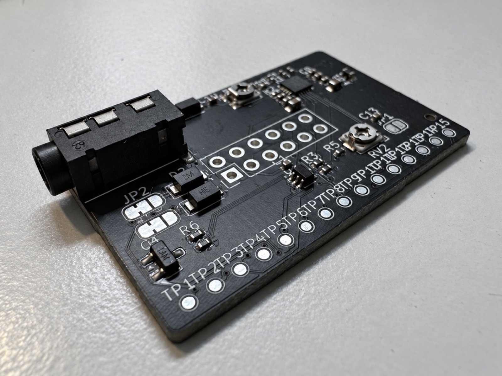 | 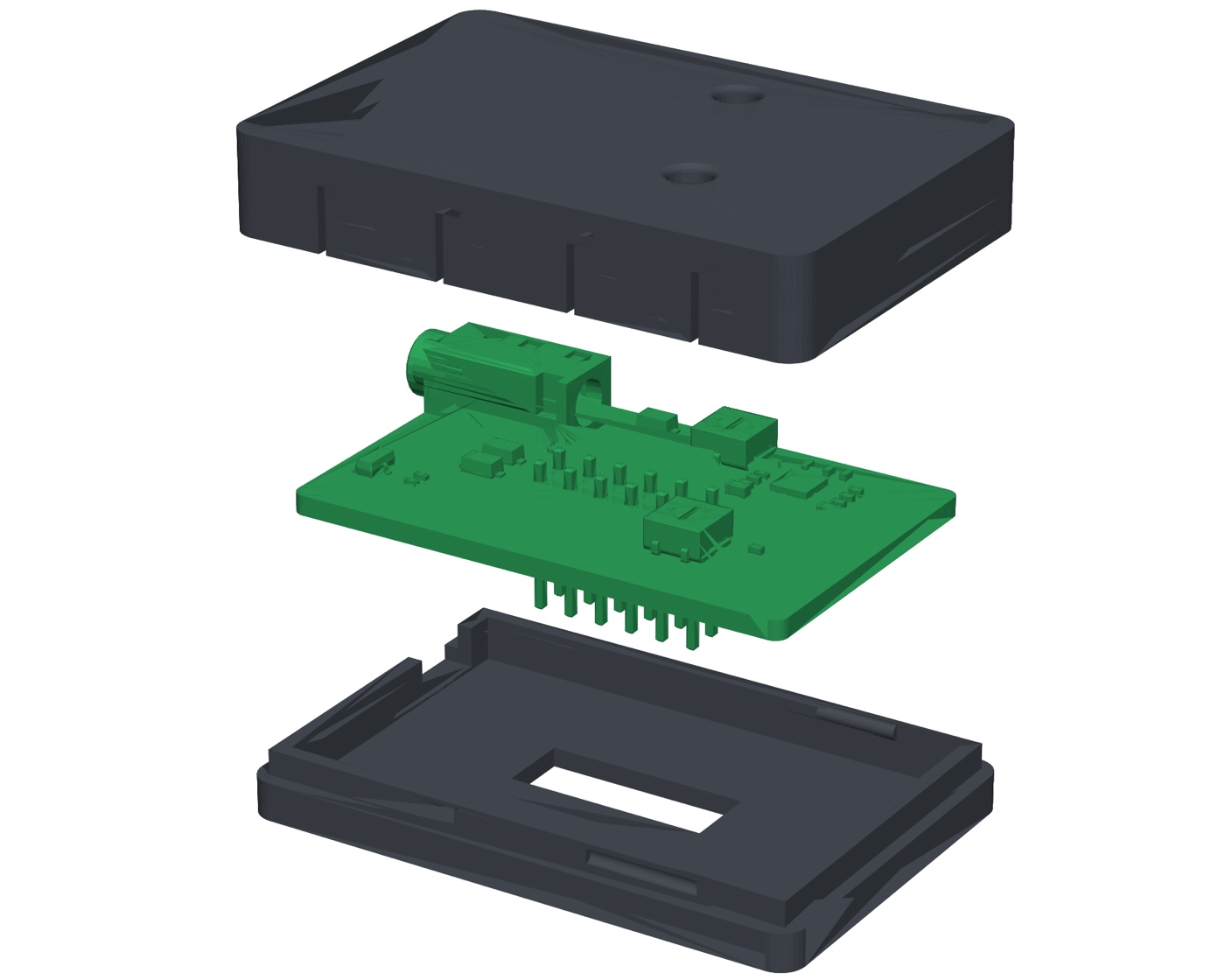 | 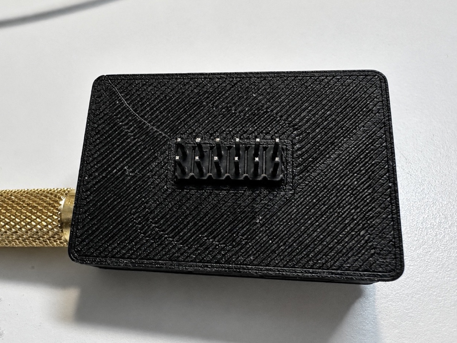 |
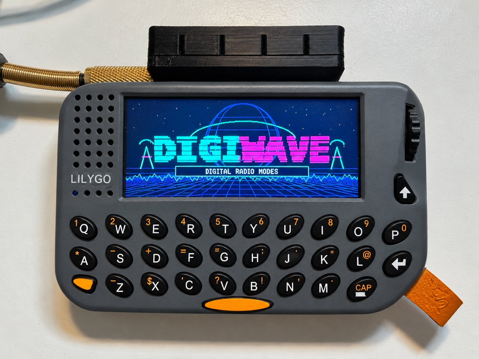
A small interface board plugs into the pager's 12-pin port. It carries its own ES8311 audio codec with line in, line out and a PTT output, and connects to the radio with one TRRS cable wired like the Digirig. The firmware uses it whenever it is plugged in (Setup, "Audio"); receive and transmit levels are set in the setup and with the two trimmers, which can be reached through the lid of its 3D-printed case.
Schematic, KiCad project, Gerber files with parts list, 3D views and the STL
files of the case are in hardware, described on its own
page.
Without the board, audio goes through the built-in microphone and speaker of the pager, so reception works held next to the speaker of any receiver.
Work in progress.
DIGIWAVE is installed as one application next to others (for example Meshtastic)
with the Launcher by bmorcelli: build
the firmware, copy .pio/build/pager/firmware.bin to the SD card and install it
from the Launcher. An update can also be written over USB straight into the
Launcher slot of DIGIWAVE (ft8pag), at the offset its partition table gives
it. The Launcher rewrites the table when applications are installed, so read it
first (esptool.py read_flash 0x8000 0xc00 table.bin); with the present table
the offset is 0x1a0000:
esptool.py write_flash 0x1a0000 .pio/build/pager/firmware.binDo not use pio run -t upload on a pager with the Launcher: it writes
partitions.csv, the layout for running DIGIWAVE alone, together with its own
bootloader, and so removes the Launcher and the other applications.
PlatformIO with the pioarduino platform (Arduino-ESP32 3.3):
pio run -e pager        # firmware
pio test -e native      # host tests of the signal processing
Artwork in DIGIWAVE_Firmware_Grafiken is converted with python3 tools/make_assets.py,
the voice announcements are spoken by Piper
with tools/make_voice.py (setup in the script).
The same everywhere:
| Wheel | select or tune: a tile, a station, the CW receive window, the RTTY tones |
| Wheel press | in the menu: open. In a mode: the list of its functions, with the keys that do the same directly |
| Enter | the main action of the mode: call the selected station, send the typed line, save the received picture |
| Backspace | one step back: typed text first, then the open list or page, then from the mode to the menu |
| Space + key | digits and symbols |
FT8 and FT4 keep a line with their keys at the bottom of the screen; the other modes use the whole screen for text, spectrum or picture.
The scanner analyses every two seconds: the wheel picks a signal on the waterfall, A goes back to the strongest, Enter opens the mode that decodes it. A guess shows once two analyses agree. "Input too quiet" means next to no audio arrives: check the cable and the level of the radio.
Every WEFAX line is kept in memory (half an hour of reception), so a picture can be saved as a whole at any time, and is saved by itself when the station's stop tone ends it. Saved pictures can be looked at on the pager (WEFAX functions, "Saved pictures") and are shown, downloaded and deleted on the phone page.
With a home network set up (Setup > Home Wi-Fi) and Wi-Fi on, the pager answers
at http://digiwave.local. A logging program on a computer in that network can
use three requests to keep its log and the pager's in step, in both directions:
| Request | |
|---|---|
GET /api/log | {"device":"DIGIWAVE", "call":"...", "qsos":12, "size":975, "station":14759, "stationqsos":92}: QSOs and size in bytes of the pager's logbook, size of the station file and the QSOs in it; a size is -1 while there is no such file |
GET /log.adi | the pager's logbook as ADIF |
POST /api/station | replaces the station file with the body (Content-Type: text/plain), which is written to the card as it arrives; answers 200 once it is in place |
Taking the logbook over. The pager only ever appends to its logbook and
never deletes from it, so it is enough to ask /api/log now and then and to
fetch /log.adi when size changed. Records may come again: match them on
your side, by call, date, time, band and mode. The file starts with a header
naming DIGIWAVE as programid, and every record carries station_callsign
and my_gridsquare of where it was worked, which is useful for portable
operation.
Sending QSOs to the pager. QSOs made elsewhere, at the home station for
instance, go into the station file. The pager marks these stations as worked in
the list of decodes and for the voice announcements, lists them in grey in the
logbook (key A) with their distance, leaves them out of the figures and never
returns them in /log.adi. The file is ADIF with these rules:
<eor>, lines up to 400 bytescall and band (for marking as worked), gridsquare and
my_gridsquare (for the distance), qso_date, time_on, mode,
submode, rst_sent, rst_rcvdstation in /api/log with the size
of what you sent last, which also catches another card in the pagerStaying awake. Each /api/log or /log.adi keeps the pager from going to
sleep for three minutes, so asking once a minute keeps it on while it is at
home. The display still goes off.
Name and safety. The pager announces its name over mDNS with an IPv4
address only. Resolve digiwave.local for IPv4: a lookup for any address
family can wait several seconds for an IPv6 answer that never comes (macOS
waits five). The interface has no password; everything in the home network can
reach it, the phone page with its transmit controls included.
lib/ft8core - hardware-independent decoders, encoders and QSO logiclib/ft8_lib - vendored kgoba/ft8_lib (MIT)src - firmware: audio and PTT interfaces, engine, user interface, web interfacetest - host tests and reference recordings from ft8_libhardware - interface board (KiCad project, schematic, fabrication files) and printed casePROJEKT.md - description of the project in GermanCopyright (C) 2026 Andres Leroi
DIGIWAVE is free software: you can redistribute it and/or modify it under the
terms of the GNU General Public License as published by the Free Software
Foundation, either version 3 of the License, or (at your option) any later
version. It comes without any warranty. The text is in LICENSE.
The hardware in hardware, interface board and case, is licensed
under the CERN Open Hardware Licence Version 2 - Strongly Reciprocal
(CERN-OHL-S-2.0), text in hardware/LICENSE.
It stands on the work of others:
The complete list with versions, authors and licences is in
THIRD-PARTY-NOTICES.md. The same credits are shown
on the device under Setup, "About DIGIWAVE".
| Qty | Value | Footprint | References |
|---|---|---|---|
| 8 | 1u | Capacitor_SMD:C_0402_1005Metric | C3, C7, C8, C9, C10, C11, C12, C13 |
| 3 | 100n | Capacitor_SMD:C_0402_1005Metric | C1, C4, C6 |
| 3 | 10k | Resistor_SMD:R_0402_1005Metric | R1, R2, R7 |
| 2 | 10u | Capacitor_SMD:C_0603_1608Metric | C2, C5 |
| 2 | SMF5.0CA | Diode_SMD:D_SOD-123F | D1, D3 |
| 1 | 100k | Resistor_SMD:R_0402_1005Metric | R4 |
| 1 | 10k RX | Potentiometer_SMD:Potentiometer_Bourns_TC33X_Vertical | RV1 |
| 1 | 10k TX | Potentiometer_SMD:Potentiometer_Bourns_TC33X_Vertical | RV2 |
| 1 | 1k | Resistor_SMD:R_0402_1005Metric | R6 |
| 1 | 33R | Resistor_SMD:R_0402_1005Metric | R3 |
| 1 | 3V3 | TestPoint:TestPoint_Pad_D1.0mm | TP9 |
| 1 | 3V3A | TestPoint:TestPoint_Pad_D1.0mm | TP10 |
| 1 | 470R | Resistor_SMD:R_0402_1005Metric | R5 |
| 1 | 600R@100MHz | Inductor_SMD:L_0603_1608Metric | FB1 |
| 1 | AGND-DGND | NetTie:NetTie-2_SMD_Pad0.5mm | NT1 |
| 1 | ASDOUT | TestPoint:TestPoint_Pad_D1.0mm | TP4 |
| 1 | BCLK | TestPoint:TestPoint_Pad_D1.0mm | TP1 |
| 1 | DATA | TestPoint:TestPoint_Pad_D1.0mm | TP3 |
| 1 | DSDIN | TestPoint:TestPoint_Pad_D1.0mm | TP5 |
| 1 | ES8311 | Package_DFN_QFN:QFN-20-1EP_3x3mm_P0.4mm_EP1.65x1.65mm | U1 |
| 1 | GND | TestPoint:TestPoint_Pad_D1.0mm | TP11 |
| 1 | LRCK | TestPoint:TestPoint_Pad_D1.0mm | TP2 |
| 1 | MCLK | TestPoint:TestPoint_Pad_D1.0mm | TP6 |
| 1 | MMBT3904 | Package_TO_SOT_SMD:SOT-23 | Q1 |
| 1 | PJ-320D TRRS | Connector_Audio:Jack_3.5mm_PJ320D_Horizontal | J2 |
| 1 | PTT_CTRL | TestPoint:TestPoint_Pad_D1.0mm | TP15 |
| 1 | Pager J3 2x6 | Connector_PinHeader_2.54mm:PinHeader_2x06_P2.54mm_Vertical | J1 |
| 1 | RING1 | TestPoint:TestPoint_Pad_D1.0mm | TP13 |
| 1 | RING2 | TestPoint:TestPoint_Pad_D1.0mm | TP14 |
| 1 | Ring1 sel | Jumper:SolderJumper-3_P1.3mm_Bridged12_RoundedPad1.0x1.5mm | JP2 |
| 1 | Ring2 sel | Jumper:SolderJumper-3_P1.3mm_Bridged12_RoundedPad1.0x1.5mm | JP3 |
| 1 | SCL | TestPoint:TestPoint_Pad_D1.0mm | TP8 |
| 1 | SDA | TestPoint:TestPoint_Pad_D1.0mm | TP7 |
| 1 | SMF15CA | Diode_SMD:D_SOD-123F | D2 |
| 1 | SN74LVC1G3157DCKR | Package_TO_SOT_SMD:SOT-363_SC-70-6 | U2 |
| 1 | TIP_RX | TestPoint:TestPoint_Pad_D1.0mm | TP12 |
| 1 | TX DC bypass | Jumper:SolderJumper-2_P1.3mm_Open_RoundedPad1.0x1.5mm | JP1 |
It measures 40 × 25 mm and has 2 copper layers, 1.6 mm thick.
50 parts, built around the ES8311, SN74LVC1G3157DCKR, SMF5.0CA and MMBT3904. The full list of its parts is on this page, with links to each part's symbol and footprint where PCBKit's library has them.
From the MrNash23/DIGIWAVE repository on GitHub, at the commit this page was made from: the board is hardware/interface-board/ft8-pager-interface.kicad_pcb and its schematic hardware/interface-board/ft8-pager-interface.kicad_sch. PCBKit opens the board in the browser, with nothing to install.
Its repository publishes it under the GPL-3.0 licence: you may reuse it on that licence's terms (keep the author's notice, and for a copyleft licence share your changes alike).


Vtechcode/stm32f303_sim7600
This is a device that is suitable for IoT and machine-to-machine communication. SIM7600E is an industrial-grade LTE Cat 1 module designed for global IoT and M2M applications.

sikaxn/FRC-Custom-CAN-Sensor
If you are looking for IronMaple ESP32‐FRC‐devkit resources, please switch branch to dev-board.

atomicra1n/wifi-geiger-counter
A DIY Geiger counter PCB which can detect ionizing radiation and log readings over Wi-Fi. Built with an ESP32, and a HV multiplier circuit that steps up 3.7V to 400V for the GM tube.

danhmanu/PLC-STM32F407VET6
Mạch nguyên lý KiCad 10 cho bộ PLC: điều khiển qua LAN bằng Modbus TCP (module W5500 Lite), nạp code qua USB‑C (CH340C), 16 ngõ ra transistor cách ly quang, 10 ngõ vào analog 4–20mA.

