
2 layers
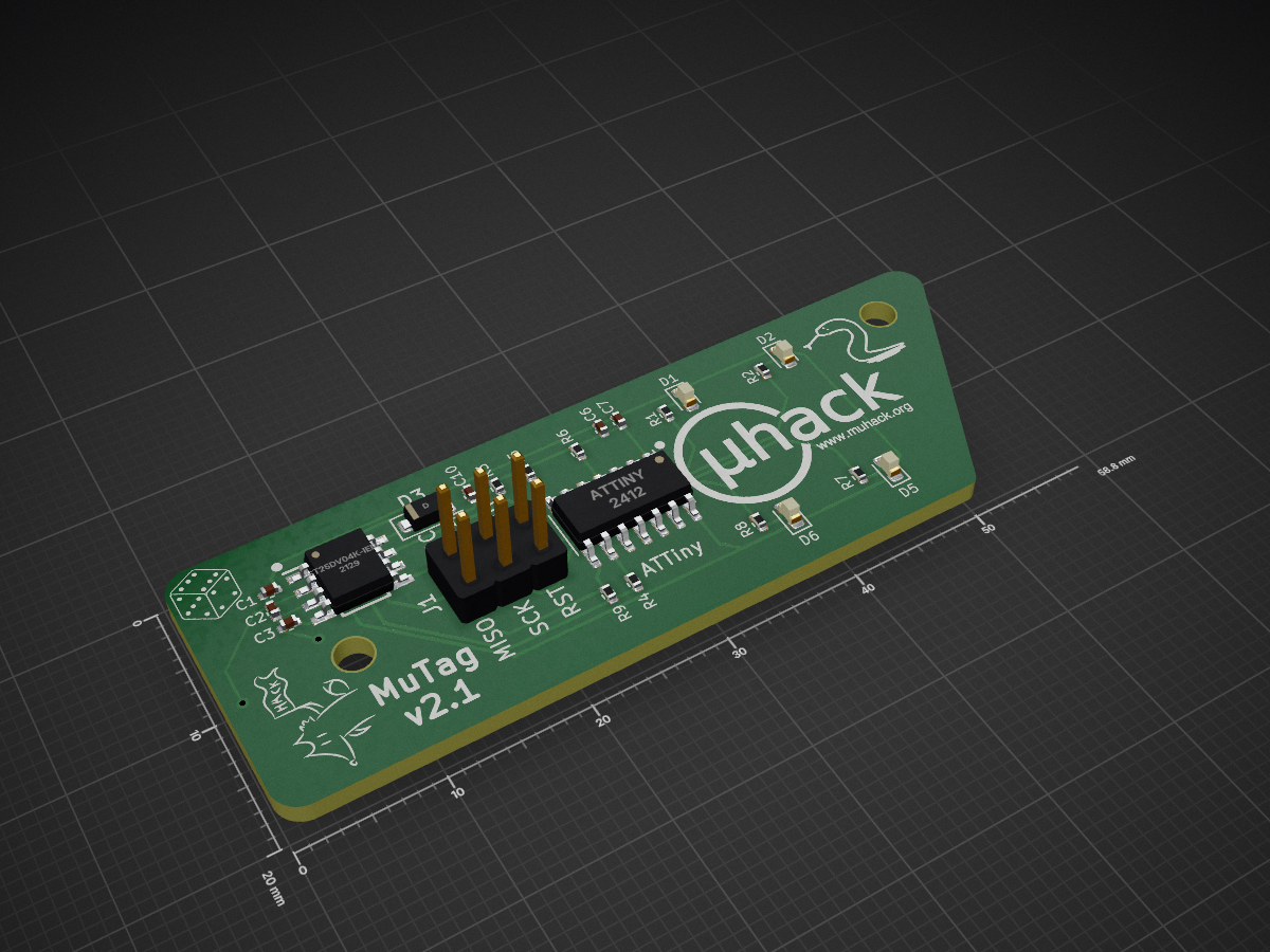
 MrMoDDoM/MuTag14
Repository for PCB and source file of the MuHack NFC Tag keychain
MuTag is an open-source printed circuit board by MrMoDDoM, from the MrMoDDoM/MuTag repository on GitHub, published under the AGPL-3.0 licence. It is a 2-layer board of 58.6 × 20 mm with 30 parts on 21 nets, routed with 150 tracks and 6 vias.
It is built around the ST25DV04K-IER6S3. Its parts include 9 resistors, 6 capacitors, 5 diodes, 2 ICs and 1 connector. It belongs with the radio and wireless boards and the AVR (ATmega, ATtiny) boards of this library.
Repository for PCB and source file of the MuHack NFC Tag keychain.
This is a custom printed circuit board featuring an ATTiny44a microcontroller and an ST25 NFC ISO15 tag.
From the MCU is it possible to access the NFC tag using I2C, to modify the tag's configuration and read/write data.
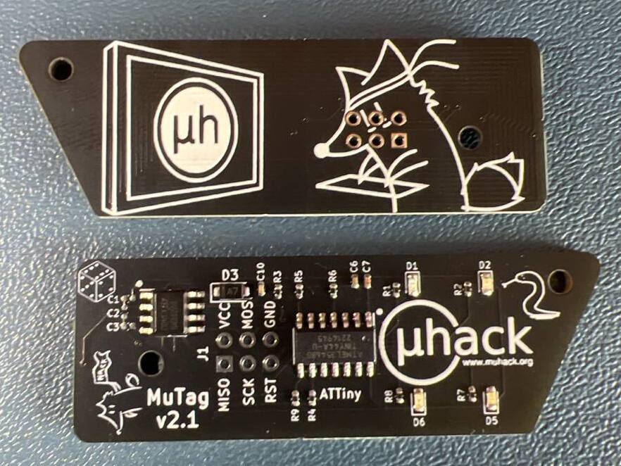
In the Hardware folder you can find the PCB design files and the schematics.
#define YELLOW_LED 0
#define GREEN_LED 1
#define BLUE_LED 2
#define RED_LED 3
The LEDs are connected to:
The NFC tag is connected to the ATTiny's I2C bus:
The NFC GPO is also connected to the ATTiny's INT0 interrupt port (Port PB2).
By default, the ST25 NFC tag is set to "on demand" energy harvesting mode. To activate energy harvesting mode on the ST25 NFC IC, you will need to use the ST25 Android app (future implementation of the software will automatically activate this through the I2C communication).
Follow these steps:
Download the ST25 Android app from the Google Play Store (https://play.google.com/store/apps/details?id=com.st.st25nfc)
Scan the tag with the ST25 Android app and from the left menu go to "Register Management"
Re-scan the tag to update the tag's configuration. You will see a register called EH_MODE. By default, this register is set to 0x01, which means that energy harvesting mode is set "on demand". To enable energy harvesting mode, change the value of this register to 0x00
While maintaining the tag in the field, tap the "Save" button to write the new configuration to the tag (the default password is all zeros, just tap "OK" to continue)
Generally speaking, the ATTiny44a MCU must be programmed using an external ISP programmer. In this case, we will use an Arduino Uno as an ISP programmer (you can use any other Arduino board that can be used as an ISP).
Flash the ArduinoISP sketch (found in the File -> Example menu) to an Arduino (or any other Arduino board that can be used as an ISP)
Add the following line to "Additional Boards Manager URLs" in the Arduino IDE preferences:
http://drazzy.com/package_drazzy.com_index.json
ATTinyCore by Spence Konde board definition (found in the Tool -> Board -> Board Manager menu) and select the following settings:| Setting | Value |
|---|---|
| Board | ATTiny24/44/84 (noBootloader) |
| Chip | ATTiny44(a) (Note: for v2.0 select 24) |
| Clock | 1 MHz internal |
| BOD | Disabled |
| LTO | Enabled |
| EEPROM | EEPROM retained |
| millis()/micros() | Enabled |
| Programmer | Arduino as ISP |
| MuTag | Arduino |
|---|---|
| VDD | 5V |
| GND | GND |
| SCK | 13 |
| MISO | 12 |
| MOSI | 11 |
| RST | 10 |
NOTE: The MuTag through hole ports are of 1.27mm diameter, enough to fit a common jumper wire. So with a little bit of patience you can push the pin rigth into the hole without soldering.
The holes dimension was changed to a standard 2.54mm in the v2.1
Take another jump wire and connect it the RESET pin of the Arduino and leave the other end unconnected
Now the tricky part: to program the MuTag we need to send the Arduino in "reset mode" for a short period of time. To do this, we need to connect the RESET pin of the Arduino to ground (i.e. by touching the USB ground shield with the unconnected end the RESET wire) rigth before we press the "Upload" button in the Arduino IDE. Wait about 2/3 seconds and then release the RESET wire. You should see the Arduino IDE uploading the sketch to the MuTag.
NOTE: Depending on your Arduino IDE version, you might need to use the "Upload using Programmer" option in the Sketch menu instead of the "Upload" button.
The internal memory of the ST25 NFC tag can be accessed through the I2C bus as a standard EEPROM memory. The I2C address of the tag is 0x53.
The "Hello_MuHack.ino" sketch is a simple example of how to read and write data to the tag.
RESET padThe bootloader is a small piece of code that is stored in the MCU's memory and that allows to program via UART. This is very useful because it avoid the need of an external SPI programmer.
The Optiboot version compiled by Spence Konde uses the pins AIN0 and AIN1, currently connected to the LEDs. This leaves us with two options:
Since this project is intended to be used as a keychain, which means that is to be programmed only once, I decided to not invest time in the bootloader and leave the LEDs as they are.
Copyright (c) 2023 MrMoDDoM
This project is licensed under the GNU AFFERO GENERAL PUBLIC License - see the LICENSE.md file for details
| Qty | Value | Footprint | References |
|---|---|---|---|
| 6 | LOGO | LOGO | G***, G***, G***, G***, G***, G*** |
| 4 | 1.5K | Resistor_SMD:R_0402_1005Metric | R3, R4, R5, R9 |
| 4 | 160 | Resistor_SMD:R_0402_1005Metric | R1, R2, R7, R8 |
| 3 | NC | Capacitor_SMD:C_0402_1005Metric | C1, C2, C3 |
| 1 | 100nF | Capacitor_SMD:C_0402_1005Metric | C6 |
| 1 | 10K | Resistor_SMD:R_0402_1005Metric | R6 |
| 1 | 10nF | Capacitor_SMD:C_0402_1005Metric | C10 |
| 1 | 1nF | Capacitor_SMD:C_0402_1005Metric | C7 |
| 1 | ATTiny | Package_SO:SOIC-14_3.9x8.7mm_P1.27mm | U2 |
| 1 | D | Diode_SMD:D_SOD-123F | D3 |
| 1 | LED_BLUE | LED_SMD:LED_0603_1608Metric | D2 |
| 1 | LED_GREEN | LED_SMD:LED_0603_1608Metric | D5 |
| 1 | LED_RED | LED_SMD:LED_0603_1608Metric | D1 |
| 1 | LED_YELLOW | LED_SMD:LED_0603_1608Metric | D6 |
| 1 | MuTag_NFC_Antenna | MuTag Antenna:mutag_new_antenna | A1 |
| 1 | SPI_Header | Connector_PinHeader_2.54mm:PinHeader_2x03_P2.54mm_Vertical | J1 |
| 1 | ST25DV04K-IER6S3 | ST25DV04K-IER6S3:SOIC127P600X175-8N | IC1 |
It measures 58.6 × 20 mm and has 2 copper layers, 1.6 mm thick.
30 parts, built around the ST25DV04K-IER6S3. The full list of its parts is on this page, with links to each part's symbol and footprint where PCBKit's library has them.
From the MrMoDDoM/MuTag repository on GitHub, at the commit this page was made from: the board is Hardware/MuTag.kicad_pcb and its schematic Hardware/MuTag.kicad_sch. PCBKit opens the board in the browser, with nothing to install.
Its repository publishes it under the AGPL-3.0 licence: you may reuse it on that licence's terms (keep the author's notice, and for a copyleft licence share your changes alike).

Teehee2/ESP-32-Business-Card
Personal Business Card with fully functional ESP-32 and NFC

google/mozc-devices
Circuit diagrams and firmware source code for Gboard DIY keyboards


VoronDesign/Voron-Hardware
Cool Hardware designed by the Voron Design group

hoglet67/RGBtoHDMI
Bare-metal Raspberry Pi project that provides pixel-perfect sampling of Retro Computer RGB/YUV video and conversion to HDMI

tenderlove/initial-v
It's a BMW shifter converted to a Bluetooth Keyboard that you use with Vim

hackclub/OnBoard
💡 Join 1,000 teenagers and make your first PCB with a $100 grant!