4 layers65.4 × 111.6 mm

 mrehkopf/ReClockator-5002
Changes the orientation of a 68000 DIP CPU, adds 4 clock ports
ReClockator-500 is an open-source printed circuit board by mrehkopf, from the mrehkopf/ReClockator-500 repository on GitHub, published under the GPL-3.0 licence. It is a 4-layer board of 97.4 × 94.7 mm with 20 parts on 93 nets, routed with 1,190 tracks and 83 vias.
It is built around the 74HCT245, 74HCT08D and 74HCT139D, with the 74HCT688D among its other parts. Its parts include 7 capacitors, 6 ICs and 4 connectors. It belongs with the retro computing and games boards of this library.


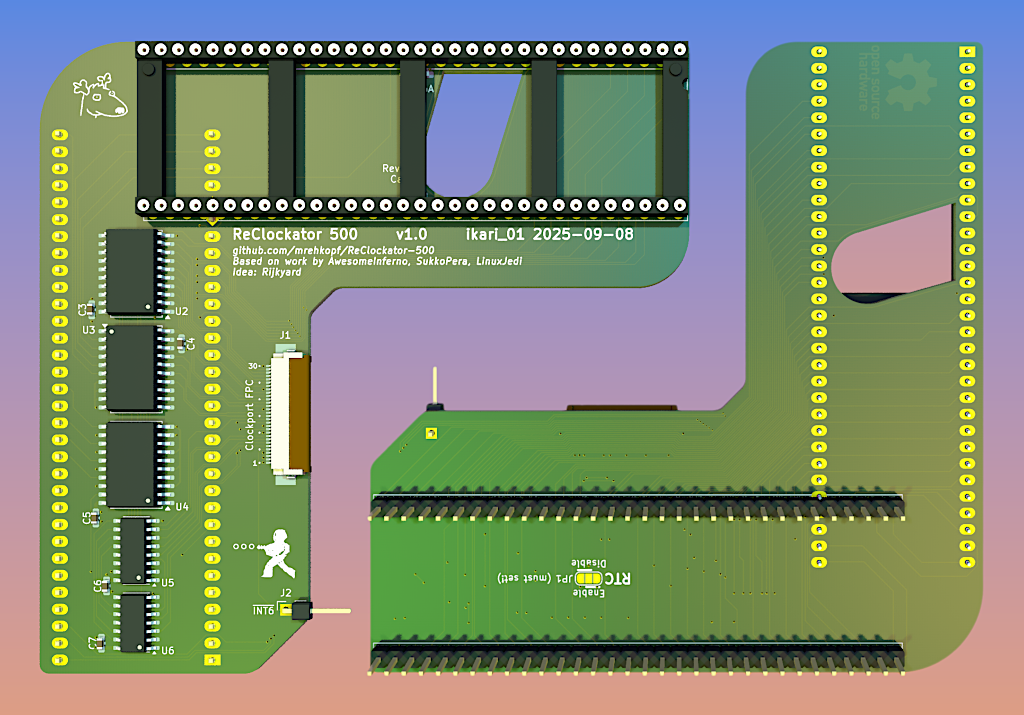
ReClockator 500 is an Open Hardware adapter PCB that changes the orientation of a 68000 DIP CPU; it is intended for use with the Amiga 500 computer to facilitate arrangement of expansions inside the case.
It also adds four clock ports and one RTC port, all available on a 30-lead FPC connector.
ReClockator 500's lineage:
I took the liberty of renaming the project because of the added clock ports on top of its relocative nature.
Four clock ports (Based on Gayle's "SPARE" mapping)
$D80001$D84001$D88001$D8C001One RTC port @$DC0001
Length-matched squiggly traces removed for space requirements
Signal names are removed from the CPU pin header to make space for the clock port decoding logic.
The pinout for the 30-lead FPC connector is as follows:
| Pin # | Function |
|---|---|
| 1 | GND |
| 2 | +5V |
| 3 | +5V |
| 4 | +5V |
| 5 | #INT6 |
| 6 | #SPARE0_CS |
| 7 | #SPARE1_CS |
| 8 | #SPARE2_CS |
| 9 | #SPARE3_CS |
| 10 | GND |
| 11 | #RTC_CS |
| 12 | #RTC_PWRBAD |
| 13 | #IORD |
| 14 | #IOWR |
| 15 | A5 |
| 16 | A4 |
| 17 | GND |
| 18 | A3 |
| 19 | A2 |
| 20 | D23 |
| 21 | D22 |
| 22 | D21 |
| 23 | GND |
| 24 | D20 |
| 25 | D19 |
| 26 | D18 |
| 27 | D17 |
| 28 | D16 |
| 29 | #RESET |
| 30 | GND |
In addition, an #INT6 pin is present on the PCB. It must be connected to the #INT6 signal on the Amiga 500 main board.
Open68000Relocator and, by extension, ReClockator 500, is Open Hardware released under the GNU General Public License (GPL) v3. If you make any modifications to the board, you must contribute them back.
Open68000Relocator and, by extension, ReClockator 500, is provided to you ‘as is’ and without any express or implied warranties whatsoever with respect to its functionality, operability or use, including, without limitation, any implied warranties of merchantability, fitness for a particular purpose or infringement. We expressly disclaim any liability whatsoever for any direct, indirect, consequential, incidental or special damages, including, without limitation, lost revenues, lost profits, losses resulting from business interruption or loss of data, regardless of the form of action or legal theory under which the liability may be asserted, even if advised of the possibility or likelihood of such damages.
| Qty | Value | Footprint | References |
|---|---|---|---|
| 7 | 100n | Capacitor_SMD:C_0603_1608Metric_Pad1.08x0.95mm_HandSolder | C1, C2, C3, C4, C5, C6, C7 |
| 2 | 74HCT245 | Package_SO:SOIC-20W_7.5x12.8mm_P1.27mm | U2, U3 |
| 1 | 68000D | Open68000Relocator:DIP-64_W22.86mm_Socket_LongPads_IC | U1 |
| 1 | 68000D | Open68000Relocator:DIP-64_W22.86mm_Socket_LongPads_Socket | P1 |
| 1 | 74HCT08 | Package_SO:SOIC-14_3.9x8.7mm_P1.27mm | U6 |
| 1 | 74HCT139 | Package_SO:SOIC-16_3.9x9.9mm_P1.27mm | U5 |
| 1 | 74HCT688 | Package_SO:SOIC-20W_7.5x12.8mm_P1.27mm | U4 |
| 1 | Conn_01x01_Pin | Connector_PinHeader_2.54mm:PinHeader_1x01_P2.54mm_Horizontal | J2 |
| 1 | Conn_01x30 | mypackages:FPC_30pin_0.5mm_average | J1 |
| 1 | LOGO | rehkopf:LOGO_9.5x8_FacingRight | G*** |
| 1 | OSHW_LOGO | Symbol:OSHW-Logo_11.4x12mm_Copper | P99 |
| 1 | RTC_Enable | Jumper:SolderJumper-3_P1.3mm_Open_RoundedPad1.0x1.5mm | JP1 |
The 19 most common of 20 parts.


Julesc013/project-carbon
Hardware and software for custom CPUs, FPUs, and computer systems.
It measures 97.4 × 94.7 mm and has 4 copper layers, 1.76 mm thick.
20 parts, built around the 74HCT245, 74HCT08D, 74HCT139D and 74HCT688D. The full list of its parts is on this page, with links to each part's symbol and footprint where PCBKit's library has them.
From the mrehkopf/ReClockator-500 repository on GitHub, at the commit this page was made from: the board is ReClockator-500.kicad_pcb and its schematic ReClockator-500.kicad_sch. PCBKit opens the board in the browser, with nothing to install.
Its repository publishes it under the GPL-3.0 licence: you may reuse it on that licence's terms (keep the author's notice, and for a copyleft licence share your changes alike).