4 layers230 × 196.7 mm
Steel form Dish washer
R-Mutura/DISHWASHER
Contains hardware and Software implementation of a dishwasher product
156 parts

 motivemachine/LORA_remote_relays
AC powered relay control board using Lora radios. Turn on lights, heaters or whatever else you need at a distance. This repo is a mirror for:
LORA Relay AC is an open-source printed circuit board by motivemachine, from the motivemachine/LORA_remote_relays repository on GitHub, published under the Apache-2.0 licence. It is a 2-layer board of 104.4 × 99.8 mm with 45 parts on 54 nets, routed with 280 tracks and 22 vias.
It is built around the HLK-PM01, AMS1117-3.3 and MMBT3904. Its parts include 14 resistors, 4 capacitors, 4 diodes, 2 transistors and 2 switches. It belongs with the radio and wireless and home automation and IoT boards and the AVR (ATmega, ATtiny) boards of this library.


AC powered relay control board using Lora radios. Turn on lights, heaters or anything else you need at a distance. The first one has been installed and running smooth for several months now! Check it out here: https://asthemillturns.serveblog.net/lora-ac-relays.html
This devices runs on 110VAC, and controls other 110VAC devices. Do not make this if you don't know what you're doing! Power traces are very conservatively rated at 8 amp total (both relays combined), further changes and testing should increase this. There is no snubber circuity on the relays, so as-is should only be used with resistive loads (lights, heaters, etc.). Small fans should be fine. Running motors should have proper circuitry in place on the relay outputs to handle any noise or back-EMF from such devices.
Board design and code for v1.1 is completed and all is running well. Board v1.2 design is complete but code has not been written yet. Code for v1.1 should work almost as-is after changing the pin numbers. Primarily the difference between 1.1 and 1.2 is that 1.1 must poll the radio for new packets while the new version will use interrupts. Other changes are improved silkscreening and more IO breakouts for other projects.
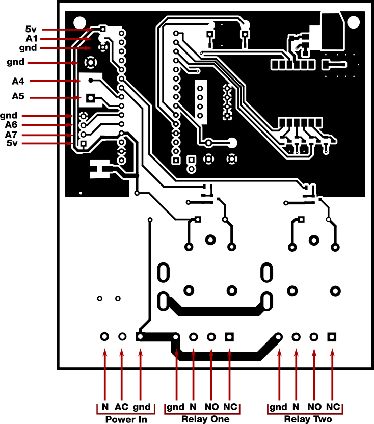
I've broken out some extra arduino pins for integration in future projects. Starting from the upper left:
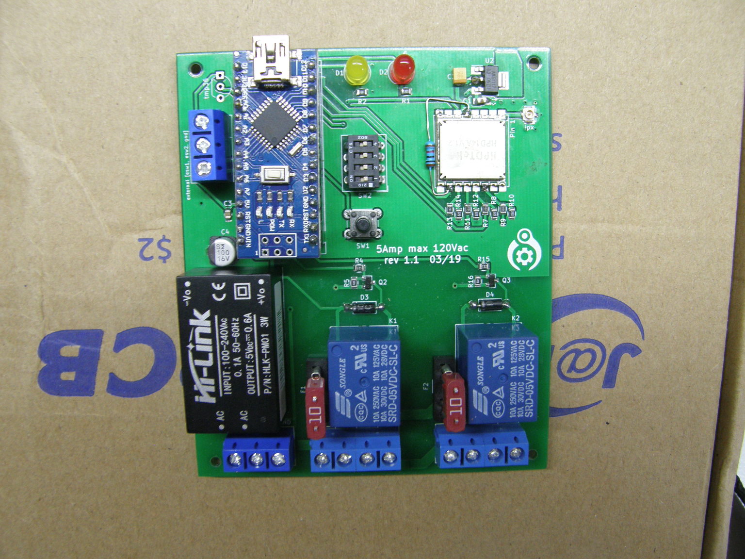
This is a photo of the complete v1.1 board. The schematics are up to date with v1.2, which adds some extra IO pins, adjusted silkscreen, and moved some parts to make them easier to work with (like moving the fuse holder farther away from the relays)
There are two PlatformIO project folders, one for the main program, one named 'circuit test'. The circuit test routing just verifies everything was connected correctly: blink leds, toggle relays, send a packet. Both programs are contained in the 'src/' folder and can be pulled from there if you wish to use the code with Arduino IDE.
Some of these software functions are in a state of change as I figure out how best to integrate these devices with my Lora home network, but the basic purpose remains the same:
| Qty | Value | Footprint | References |
|---|---|---|---|
| 4 | 1k | Resistors_SMD:R_0805 | R7, R9, R11, R13 |
| 4 | 2k | Resistors_SMD:R_0805 | R8, R10, R12, R14 |
| 4 | MountingHole | Mounting_Holes:MountingHole_2.5mm | H1, H2, H3, H4 |
| 2 | 100 | Resistors_SMD:R_0805 | R4, R15 |
| 2 | 10k | Resistors_SMD:R_0805 | R5, R16 |
| 2 | 3k3 | Resistors_SMD:R_0805 | R1, R2 |
| 2 | 4001 | Diodes_THT:D_A-405_P7.62mm_Horizontal | D3, D4 |
| 2 | Fuse | Fuse_Holders_and_Fuses:BladeFuse-Mini | F1, F2 |
| 2 | LED | LEDs:LED_D5.0mm | D1, D2 |
| 2 | MMBT3904 | TO_SOT_Packages_SMD:SOT-23 | Q2, Q3 |
| 1 | .1uf | Capacitors_SMD:C_0805 | C3 |
| 1 | 100uf | Capacitors_SMD:CP_Elec_5x5.3 | C4 |
| 1 | 1uf | Capacitors_SMD:C_0805_HandSoldering | C1 |
| 1 | 22uf | Capacitors_SMD:C_0805_HandSoldering | C2 |
| 1 | ACin | TerminalBlocks_Phoenix:TerminalBlock_Phoenix_MKDS1.5-3pol | N AC GND |
| 1 | AMS1117-3.3 | TO_SOT_Packages_SMD:SOT-223-3_TabPin2 | U2 |
| 1 | ArduinoNano | MainWorking:ArduinoNano | ATMEGA328p_nano |
| 1 | HLK-PM01 | MainWorking:HLK-PM01 | HLK-PM01 |
| 1 | LOGO_MWM_med | MainWorking:LOGO_MWM_med | G*** |
| 1 | SW_DIP_x04 | Buttons_Switches_THT:SW_DIP_x4_W7.62mm_Slide | SW2 |
| 1 | SW_Push | Buttons_Switches_THT:SW_PUSH_6mm_h4.3mm | SW1 |
| 1 | Sx1278_LORA_Module | MainWorking:LORA_SX1278_Module | LORA_EE1 |
| 1 | external_Sw | TerminalBlocks_Phoenix:TerminalBlock_Phoenix_MKDS1.5-3pol | external [esw1, esw2, gnd] |
| 1 | relay1 | TerminalBlocks_Phoenix:TerminalBlock_Phoenix_MKDS1.5-4pol | Gnd Neut NO NC |
| 1 | relay1 | Relays_THT:Relay_SPDT_SANYOU_SRD_Series_Form_C | Relay1 |
| 1 | relay2 | TerminalBlocks_Phoenix:TerminalBlock_Phoenix_MKDS1.5-4pol | Gnd Neut NO NC |
| 1 | relay2 | Relays_THT:Relay_SPDT_SANYOU_SRD_Series_Form_C | Relay2 |
| 1 | sma | Connectors_Molex:Molex_Microcoaxial_RF | ipx |
| 1 | tmp36 | TO_SOT_Packages_THT:TO-92_Inline_Wide | tmp36 |
R-Mutura/DISHWASHER
Contains hardware and Software implementation of a dishwasher product

gnilsson2/YAPP_Box_KiCad_Generator
Generate Openscad boxes from KiCad PCB files.

controlol/led-driver-constant-current-esphome
KiCad design for a constant current driver with Mean Well dimmable LED driver and ESPHome firmware

yabo104/Electric_Door_With_ESP32_S3
This proyeject contains a hardware/firmware development for an electric door controller.

milar111/HEAT
An open-source STM32 SMD assembly station for precision soldering. Uses a custom Smart Pulse & Coast algorithm to drive 400W mains heaters via SSR. Features OLED UI, NTC feedback, and safety cooling.

NguyenThanhHuy-debug/PCB-Liquid-Dispensing-Cabinet
PCB-Liquid-Dispensing-Cabinet — a software project built with modern tooling.


Noraiz963/Home-Automation-by-using-esp32_WROOM32D-pcb-
An ESP32-based home automation controller designed in KiCad combines an isolated AC-DC power supply, dual relay outputs, physical switch input, and UART programming header into a single board for controlling AC loads…
It measures 104.4 × 99.8 mm and has 2 copper layers, 1.6 mm thick.
45 parts, built around the HLK-PM01, AMS1117-3.3 and MMBT3904. The full list of its parts is on this page, with links to each part's symbol and footprint where PCBKit's library has them.
From the motivemachine/LORA_remote_relays repository on GitHub, at the commit this page was made from: the board is hardware/v1.1/LORA_Relay_AC.kicad_pcb. PCBKit opens the board in the browser, with nothing to install.
Its repository publishes it under the Apache-2.0 licence: you may reuse it on that licence's terms (keep the author's notice, and for a copyleft licence share your changes alike).